4. Heat Radiation and Installation
Design and Build the system considering the size of the controller box, location of the controller and
cooling factors to keep the surrounding temperature around the controller below 40°C.
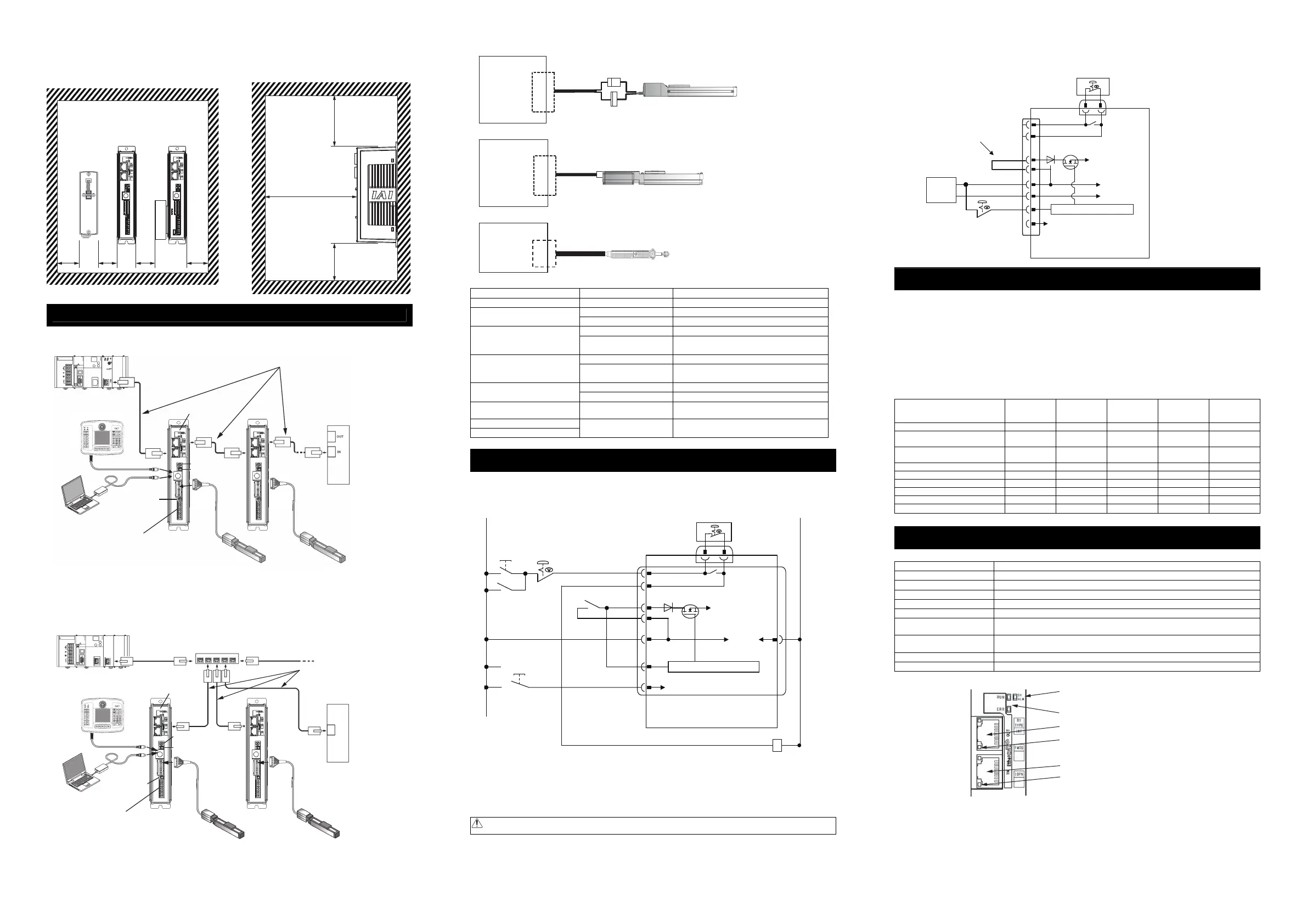
Connection Diagram
● EtherCAT®
(Note 1) STP (with shield) is recommended for Ethernet cable.
(Note 2) It is necessary to prepare a power supply cable and the cables for the emergency stop circuit
wiring as well as this cable. [Refer to power supply and emergency stop circuit.]
● For EtherNet/IP and PROFINET-IO
(Note 1) STP (with shield) is recommended for Ethernet cable.
(Note 2) It is necessary to prepare a power supply cable and the cables for the emergency stop circuit
wiring as well as this cable. [Refer to power supply and emergency stop circuit.]
● Connection to RCP2 (High-Thrust), RCA and RCL Series
PCON
ACON
Motor/
Encoder Connector
Connection
Cable
(Note
1
)
● Connection to RCP3, RCP4, RCP5, RCP6 and RCA2 Series
Connection
Cable
(Note
1
)
PCON
ACON
Motor/
Encoder Connector
● Connection to RCD Series
DCON
Connection
Cable
(Note
1
)
Motor/
Encoder Connector
Note 1 Applicable Connection Cable Model Codes □□□ : Cable Length Example) 030 = 3m
Model Name Cable Reference
RCP2 CB-PSEP-MPA□□□ Robot cable from 0.5 to 20m
CB-APSEP-MPA□□□ Robot cable from 0.5 to 20m
RCP3
CB-APSEP-MPA□□□-LC Standard cable from 0.5 to 20m
CB-CAN-MPA□□□-RB Robot cable from 0.5 to 20m
RCP4 (Other Than GR*Type)
RCD (Applicable Controller
Symbol : D3)
CB-CAN-MPA□□□ Standard cable from 0.5 to 20m
CB-CAN-MPA□□□-RB Robot cable from 0.5 to 20m
RCP4 (GR*Type), RCP5
RCD (Applicable Controller
Symbol : D5)
CB-CAN-MPA□□□ Standard cable from 0.5 to 20m
CB-CFA-MPA□□□ Standard cable for CFA type from 0.5 to 20m
High-Thrust
CB-CFA-MPA□□□-RB Robot cable for CFA type from 0.5 to 20m
RCA, RCL (Incremental Type)
CB-ASEP-MPA□□□
CB-ASEP2-MPA□□□
Robot cable from 0.5 to 20m
RCA (Serial Absolute Type)
RCA2
CB-APSEP-MPA□□□ Robot cable from 0.5 to 20m
Power Supply and Emergency Stop Circuit
This shows the circuit example when the emergency stop switch in the teaching pendant is enabled on the
emergency stop circuit to be built up by the client.
In the example below, uses PCON-CA. It is the same in case of except for PCON-CA.
Note 1 : The safety categories complied type (CGB Type, etc.) is not equipped with the relay to have the controller
automatically identify that a teaching tool was plugged in and switch the wiring layout. Those other than the safety
categories complied type do the automatic identification and have S1 and S2 short-circuited.
Note 2 : When the motor driving source is cut off externally for a compliance with the safety category, connect a contact
such as a contactor to the wires between MPI and MPO. Also, the ratings for the emergency stop signal that turns
ON/OFF at the contact CR1 are 24V DC and 10mA or less.
Note 3 : For CR1, select the one with coil current 0.1A or less.
Caution If supplying power with using a 24V DC, having it turned ON/OFF, keep the 0V connected and have the
+24V supplied/cut (cut one side only).
[Reference] Example for operating an actuator by using the standard type (CA or CB Type) with optimum
wiring layout
(Note) In this example, the emergency stop switch on the teaching pendant would not work.
Operation Modes and Functions (Common to Each Fieldbus)
The machine can be operated selecting one mode from the following five operation modes.
(1) Remote I/O Mode : This is the method where the operation through PIO (24V I/O) is performed using the fieldbus.
(2) Position/ : This is the method where the machine is operated by means of directly specifying the target
Simple Direct position using numerical values.
Value Mode For the speed, acceleration, deceleration, or positioning width, the already registered position
data values are used.
(3) Half Direct Value Mode : In this operation mode, in addition to the target position, the speed, acceleration, deceleration
and push current value are directly specified using numerical values.
(4) Full Direct Value Mode : In this operation mode, all the values related to the position control, are directly specified using
numerical values.
(5) Remote I/O Mode 2 : Additionally, the current position and current speed reading functions are added to the remote I/O
mode.
Operation Modes and Main Functions
Main Functions
Remote I/O
Mode
Position/
Simple Direct
Value Mode
Half Direct
Value Mode
Full Direct Value
Mode
Remote I/O
Mode 2
No. of Occupied Bytes 2 8 16 32 12
Operation with the Position No.
Specified
{ { ¯ ¯ {
Operation with the Position Data
Specified
¯ { (Note) { { ¯
Speed and Acceleration Direct Setup ¯ ¯ { { ¯
Pressing Operation { { { { {
Current Position Read ¯ { { { {
Current Speed Read ¯ ¯ { { {
Completion Position No. Read { { ¯ ¯ {
Max. Number of position table 512 768 Unused Unused 512
(Note) The actuator is operated by specifying all position data, other than the position, using a position number.
EtherCAT®
● Specification
Item Specification
Communication Protocol IEC61158Type12
Physical Layer 100BASE-TX (IEEE802.3)
Communication Frequency Automatic following to the Master
Communication Cable Length Depends on EtherCAT® Type (Distance between each node: 100m max.)
Slave Type I/O slave
Applicable Node Address
0 to 127
(17 to 80 : When connected to the master (CJ1W-NC*81) manufactured by OMRON)
Communication Cable
Category 5e or more
(Double shielded cable braided with aluminum foil recommended)
Connector RJ45 Connector × 2pcs (Input × 1, Output × 1)
Connection Daisy chain only
● Interface Section
(Note) Refer to the troubleshooting or the Instruction Manual for the details of LED displays.
MIN.
30mm
MIN.
30mm
MIN.
30mm
MIN.
30mm
MIN. 100mm
MIN. 50mm
MIN. 100mm
Ensure enough space
for wiring.
Status Display LED
Status LED (RUN/ERR)
EtherCAT® Output Port
Link/Activity LED (Output)
EtherCAT® Input Port
Link/Activity LED (Input)
Host System (PLC)
Ethernet Straight Cable
(Note 1)
(general-purpose cable, Category 5e or more)
Status Display LED
Status LED
Brake Release
Switch
PC Software
(Option)
Power Supply Terminal
(Note 2)
Actuator Actuator
I/O Slave, etc.
Axis No.
Setting Switch
Operation Mode
Setting Switch
Touch Panel Teaching
(Option)
Hub
Actuator Actuator
Host System (PLC)
Ethernet
Straight Cable
(Note 1)
Ethernet
Straight Cable
(Note 1)
Status Display LED
Status LED
(general-purpose cable,
Category 5e or more)
I/O Slave, etc.
Power Supply Terminal
(Note 2)
PC Software
(Option)
Brake Release
Switch
Axis No. Setting Switch
Operation Mode
Setting Switch
Touch Panel Teaching
(Option)
S1
S2
MPI
MPO
24V
0V
24V
0V
EMG-
BKLS
Power Supply
Connector
Emergency-stop
Switch on the
Teaching Pendant
Control
Power
Supply
SIO Connector
Wiring Condected
at Delivery
24V DC
Power Supply
Motor Power Supply
Emergency Stop Control Circuit
Brake Release Power Supply
(Note) Supply 24V when connecting actuator
equipped with brake and release brake
compulsorily
Emergency
-stop Switch
24V 0V
0V
Emergency
Stop Reset
Switch
Emergency
Stop Switch
CR1
S1
S2
MPI
MPO
24V
EMG-
BKLS
CR1
(Note 3)
Brake Forced
Release Switch
Power Supply
Connector
PCON-CA
Emergency-stop
Switch on the
Teaching Pendant
Control
Power
Supply
SIO Connector
(Note 1)
Motor Power Supply
CR2
(Note 2)
Emergency Stop Control Circuit
Brake Release Power Supply
(Note) Supply 24V when connecting actuator
equipped with brake and release brake
compulsorily

 Loading...


