NS
MS
SV
ALM
Status indicator LEDs
BS-
BDL
BDH
BS+
Monitor LED : The board operation status and network conditions can be obtained.
CompoNet Communication Connector : XW7D-PB4-R (OMRON)
DO on the PCON / ACON / DCON side and Output Data Register
Remote I/O Mode
Position / Simple
Direct Value Mode
Half Direct Value
Mode
Full Direct Value
Mode
*4
Remote I/O Mode2
Parameter No.84 : 0
(Set in delivery)
Parameter No.84 : 1 Parameter No.84 : 2 Parameter No.84 : 3 Parameter No.84 : 4
PLC Output
Area
*3
Number of Occupied
Channels : 1CH
Number of Occupied
Channels : 4CH
Number of Occupied
Channels : 8CH
Number of Occupied
Channels : 16CH
Number of Occupied
Channels : 6CH
n+6 Alarm Code Alarm Code
n+7 Status Signal
n+8
n+9
Occupied Domain
n+10
n+11
Total Number of
Movement
n+12
n+13
Total Number of
Drive
n+14 Status Signal 1
n+15
Status Signal 2
*1 The Occupied Domain shows the domain to be occupied with the operation mode setting.
Therefore, this domain cannot be used for any other purpose. Also, be careful of using duplicated node addresses.
*2 When an alarm is sounded, the completion position No. (4 bits for PM1 to PM8) shows the simple alarm code.
*3 The unit differs for each field network.
・DeviceNet or CompoNet : CH Number
・PROFIBUS-DP or MECHATROLINK : byte address
*4 It is not applicable for MECHATROLINK-Ⅰ/Ⅱ
DeviceNet
● Specification
Refer to section DeviceNet instruction manual (ME0256).
● Interface Section
LED color
Indication
Status
Description
Illuminating
Normal operation
GN
Flashing
Hardware Error. It might be recovered with reconnect of the power.
Illuminating
Hardware Error. The replacement of the board is required.
OR
Flashing
It is a minor error such as a user setting error or configuration error.
It can be recovered by re-setting, etc.
MS
-
OFF
The DeviceNet is being initialized, or the power is not supplied.
Illuminating
The connection has been established and the communication is
being performed normally.
GN
Flashing
The machine is on-line, but the connection has not been
established. Communication Stop (Network is normal).
Illuminating
Node address is duplicated or Busoff is detected.
Communication Unavailable.
OR
Flashing
Communication Error (Communication Time-out Detection)
NS
- OFF
The machine is not on-line.
The power to the DeviceNet is not supplied.
● Wiring
● Operation Mode Setting and Address Allocation
The operation mode is set using the parameters.
Set the mode change switch on the front of the board to “MANU” side and set the parameter No. 84 “FMOD: Fieldbus
Operation Mode” using the Personal Computer Application Software for RC. [Refer to Address Map]
● Station No. Setting
The station No. is set using specific parameters.
Set the parameter No.85 “NADR: Fieldbus Node Address” using the personal computer application software for RC.
Settable Range:0 to 63 (It is set to “63” when the machine is delivered from the factory.)
● Communication Speed Setting
The setting for the communication speed is not required because it automatically follows the master’s communication speed.
(Note)
After the parameter setting, cycle the control power, and return the mode toggle switch on the front of the controller to “AUTO” side.
CC-Link
● Specification
Refer to section CC-Link instruction manual (ME0254).
● Interface Section
LED Color
Indication
Status
Indication Description
(Meaning of the Indication)
Illuminating
• An error occurs.
(CRC Error/Station No. (parameters) Setting
Error/Baud Rate Setting (parameters) Error)
• Period between the power injection or software
reset and the CC-Link initialization completion
OFF • Under Normal Communication
ERR OR
Flashing
• Station No. setting or communication speed
setting is changed during the communication.
Illuminating • Under communication
RUN GN
OFF • Not communicated
● Wiring
● Operation Mode Setting and Address Allocation
The operation mode is set using the parameters.
Set the mode change switch on the front of the board to “MANU” side and set the parameter No.84 “FMOD:
Fieldbus Operation Mode” using the Personal Computer Application Software for RC.
● Station No. Setting
The station No. is set using specific parameters.
Set the parameter No.85 “NADR: Fieldbus Node Address” using the personal computer application software for RC.
Settable Range : 1 to 64 (Already set in system delivery)
● Communication Speed Setting
Set the parameter No.86 “FBRS: Fieldbus Communication Speed” using the personal computer application
software for RC.
Set Value Communications speed
0 (Set in delivery) 156kbps
1 625kbps
2 2.5Mbps
3 5Mbps
4 10Mbps
(Note) Set the Station Data for the Master Station to “ver 1, Remote Device Station”.
(Note) After the parameter setting, cycle the control power, and return the mode toggle switch on the front of the
controller to “AUTO” side.
PROFIBUS-DP
● Specification
Refer to section PROFIBUS-DP instruction manual (ME0258).
● Interface Section
LED Color
Indication
Status
Indication Description (Meaning of the Indication)
Illuminating
The communication is being performed normally from the
fieldbus in online mode.
GN
Flashing The machine is in offline mode from the fieldbus
NS
OR Flashing A communication error is caused.
Illuminating The machine is in the normal operation.
GN
Flashing Preparation for the operation is performed.
MS
OR Illuminating
A communication hardware error was detected in the
operation preparation mode.
Pin No. Description Contents
3 B-Line RxD·TxD(Communication Line on the Plus Terminal Side)
5 GND Signal Cable Grounding (Insulated)
6 +5V +5V Output (Insulated)
8 A-Line /RxD·/TxD (Signal Line on the Minus Terminal Side)
Housing Shield Cable Shield (for Case and Connection)
● Wiring
● Bus Terminal Treatment
When the line is connected to the network terminal, connect the terminal resistance to the
PROFIBUS-DP communication connector as shown in the following figure, or use the connector with the
terminal resistance.
•
Example of using the connector with the terminal resistance : SUBCON-PLUS-PROFIB/AX/SC (PHOENIX CONTACT)
• Connection of the Terminal Resistance
● Operation Mode Setting and Address Allocation
The operation mode is set using the parameters.
Set the mode change switch on the front of the board to “MANU” side and set the parameter No. 84 “FMOD :
Fieldbus Operation Mode” using the Personal Computer Application Software for RC.
● Station No. Setting
The station No. is set using specific parameters.
Set the parameter No.85 “NADR: Fieldbus Node Address” using the personal computer application software for RC.
Settable Range : 0 to 125 (It is set to “1” when the machine is delivered from the factory.)
● Communication Speed Setting
The setting for the communication speed is not required because it automatically follows the master’s
communication speed.
(Note) After the parameter setting, cycle the control power, and return the mode toggle switch on the front of the
controller to “AUTO” side.
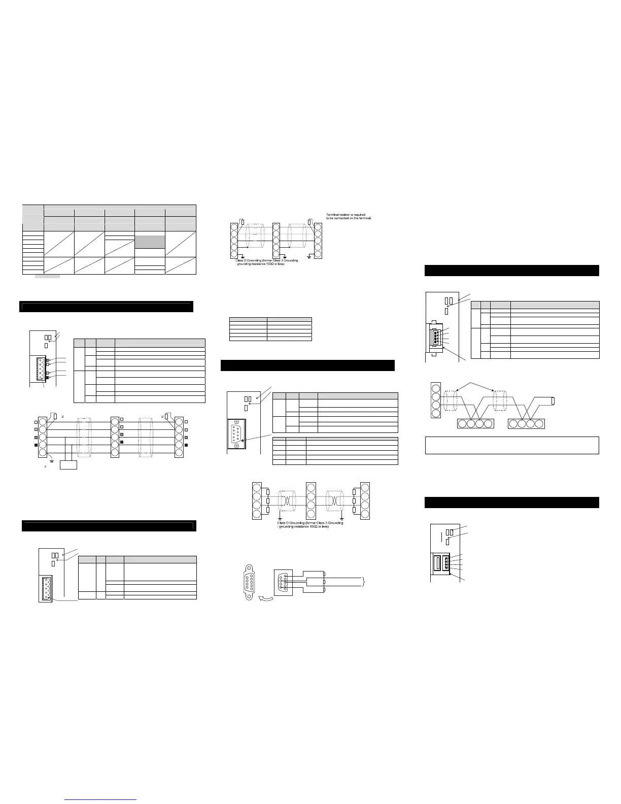
CompoNet
● Specification
Refer to section CompoNet instruction manual (ME0220).
● Interface Section
LED Color
Indication
Status
Description
GN Illuminating In the normal operation
Illuminating Hardware Error. The replacement of the board is required.
RD
Flashing
It is a minor error such as a user setting error or configuration
error. It can be recovered by re-setting, etc.
MS
- OFF The CompoNet is being initialized, or the power is not supplied.
Illuminating
The connection has been established and the communication is
being performed normally.
GN
Flashing
The machine is on-line, but the connection has not been
established. Communication Stop (Network is normal).
Illuminating A duplicated node address is considered.
RD
Flashing Communication Error (Communication Time-out Detection)
NS
- OFF
The machine is not on-line.
The power is not supplied.
● Wiring
* Comnication supply power is not required.
However, when multiple power supply is to be conducted to another slave, there would be no problem
even if connecting to the communication power to BS+ and BS- terminals.
● Station No. Setting
The station No. is set using specific parameters.
Set the parameter No.85 “NADR: Fieldbus Node Address” using the personal computer application software for RC.
Settable Range : 0 to 63 (It is set to “0” when the machine is delivered from the factory.)
(Note) The setting for the communication speed is not required because it automatically follows the master’s
communication speed.
(Note) After the parameter setting, cycle the control power, and return the mode toggle switch on the front of the
controller to “AUTO” side.
MECHATROLINK-Ⅰ/Ⅱ
● Specification
Refer to section MECHATROLINK instruction manual (ME0221).
● Interface Section
NS
MS
SV
ALM
Red
White
Blue
Black
DeviceNet Communication
Connector
: MSTB2.5/5-GF-5.08AU
(PHOENIX CONTACT)
Status indicator LEDs
Monitor LED : The board operation status and network conditions can be obtained.
ERR
SV
ALM
FG
SLD
DG
DB
DA
Status indicator LEDs
Status LED : The board operation status and network conditions can be obtained.
CC-Link Communication Connector : MSTB2.5/5-GF-5.08AU (PHOENIX CONTACT)
RUN
* Prepare for 9 pin male D-sub connector at Cable side connector.
NS
SV
ALM
Status indicator LEDs
Status LED : The board operation status and network conditions can be obtained.
PROFIBUS-DP Communication Connector : 9 pin female D-sub
MS
1
STATUS
0
SV
ALM
Status LED : The board operation status and network conditions can be obtained.
Status indicator LEDs
MECHATROLINK Communication Connector : DUSB-ARB82-T11A-FA (DDK)
NC
/DATA
DATA
SH

 Loading...


