● RCS2-RA13R Equipped with no Brake, with Loadcell in SCON-CA
● RCS2-RA13R Equipped with Brake and Loadcell in SCON-CA
Power Supply and Emergency Stop Circuit
● Wiring for Power Supply (to be prepared by customer)
NF
*3
SK
*2
+24V
0V
L1
L2
L1C
L2C
NC
PE
BK+
PWR-
100V AC
or
200V AC
(Refer to Controller
Power Voltage Specifications)
Circuit
Breaker
Ground Fault
Circuit
Interrupter
CLF
*1
Class D grounding
(Formerly Class-III grounding)
24V DC
Power
Supply
SCON
AC Power Supply
Input Connector
B. Motor Power Unit
A. Control power supply
Brake Power Supply
Input Connector
Brake
Release Box
Power consumption of SCON varies depending on the connected actuator, etc. Select the circuit breaker that suits to the
specification.
[Refer to Basic Specifications]
A ground fault circuit interrupter needs to be selected carefully considering the purposes of prevention of fire and protection
of human.
Have a measurement of the leak current where a ground fault circuit interrupter is to be installed.
Use the “harmonic type” for the ground fault circuit interrupter.
*1 CLF : Clamp Filter … It is recommended to attach it to improve noise immunity.
*2 SK : Surge Killer … It is recommended to attach it to improve noise immunity.
*3 NF : Noise Filter … Make sure to install it. It is recommended to have it installed within 0.3m of the cable length from
SCON.
Parts Name Maker Model
CLF Clamp Filter TDK ZCAT3035-1330
SK Surge Protector Okaya ELECTRIC CO.,LTD R·A·V-781BWZ-2A
COSEL NAC-10-472
SOSHIN ELECTRIC CO.,LTD NF2010-UP
NF Noise Filter
DENSEI-LAMBDA MC1210
● Wiring for Emergency Stop Input
The following diagram shows an example of how the emergency stop switch for the teaching pendant may be
included in the emergency stop circuit you may construct.
Note 1 When the teaching pendant is not connected, S1 and S2 become short-circuited inside the controller.
Note 2 Connect a contactor to L1 and L2 terminals for external power cutoff by the emergency stop if the motor power is
required to be cut off externally to comply with the Safety Categories.
Note 3 The rating for the emergency stop signal to turn ON/OFF at contact CR1 is 24V DC and 10mA.
Note 4 For CR1, select the one with coil current 0.1A or less.
Operation Modes and Functions (in common for each Fieldbus)
SCON-CA Type is available for all the operation modes in the next table.
SCON-CAL/CGAL Type is available for the operations in the modes except for those in the shaded area in
the next table.
(1) Remote I/O Mode : This is the mode to perform operation by PIO (24V I/O) with Fieldbus.
(2) Position / : This is the mode to perform operation by indicating the target position by inputting the value directly.
Simple Direct Mode The values of the position data already registered for the speed, acceleration/deceleration and
positioning band are to be used in this mode.
(3) Half Direct Mode : This is the operation mode to indicate the speed, acceleration/deceleration and pressing
current, as well as the target position, by inputting the values directly.
(4) Full Direct Mode :
This is the operation mode to indicate all related to the position control by inputting the values directly.
(5) Remote I/O Mode 2 :
This is the mode that the function to read the current position and the current speed is added to Remote I/O.
(6) Position / : This is the mode corresponding to the force control function instead of the teaching and zone
Simple Direct Mode 2 functions in (2).
(7) Half Direct Mode 2 :
This is the mode that enables to read the loadcell data instead of reading the command current value in (3).
(8) Remote I/O Mode 3 :
This is the mode that the function to read the current position and loadcell data is added to (1) functions.
(9) Half Direct Mode 3 : This is the mode that equips the vibration control function instead of the jog function in (3).
Operation Modes and Main Functions
Corresponding
Type
All the
Types
CA/CAL/CGAL Type
Dedicated for CA Type
CA/CAL/
CGAL Type
Main Functions
Remote I/O
Mode
Position /
Simple Direct
Mode
Half Direct
Mode
Full Direct
Mode
Remote I/O
Mode 2
Position /
Simple Direct
Mode 2
Half Direct
Mode 2
Remote I/O
Mode 3
Half Direct
Mode 3
Occupied Bytes
2 8 16 32 12 8 16 12 16
Position No.
Designated
Operation
○ ○ × × ○ ○ × ○ ×
Position Data
Designated
Operation
× ○
(Note 1)
○ ○ × ○
(Note 1)
○ × ○
Speed, Acceleration
and Deceleration
Direct Designation
× × ○ ○ × × ○ × ○
Pressing
Operation
○ ○ ○ ○ ○
○ ○ ○ ○
Current Position
Reading
× ○ ○ ○ ○ ○ ○ ○ ○
Current Speed
Reading
× × ○ ○ × × ○ × ○
Completed Position
No. Reading
○ ○ × × ○ ○ × ○ ×
Max. Number of
Position Tables
512 768
Not
Applicable
Not
Applicable
512 768
Not
Applicable
512
Not
Applicable
Force Control
(Specified only
for SCON-CA)
△
(Note 2)
× × ○ △
(Note 2)
○ ○ △
(Note 2)
×
Vibration Control
○
○ × ○ ○ ○ × ○ ○
Servo Gain
Changeover
○ ○ ○ ○ ○
○ × ○ ○
(Note 1) Operation is to be performed with designating the position No. for the position data except for Position Data.
(Note 2) It is available when the PIO pattern is set on either 6 or 7. However, SCON-CAL/CGAL is not applicable for PIO
Patterns 6 and 7.
EtherCAT®
● Specification
Item Specification
Communication protocol IEC61158Type12
Physical layer 100BASE-TX (IEEE802.3)
Communication speed Automatically follows the Master
Communication cable
length
Depends on EtherCAT® Specification (Distance between each node: 100m
max.)
Slave type I/O slave
Applicable node address 0 to 127
(17 to 80 : When connected to the master (CJ1W-NC*82) manufactured by
OMRON)
Communication cable Category 5e or more
(Double shielded cable braided with aluminum foil recommended)
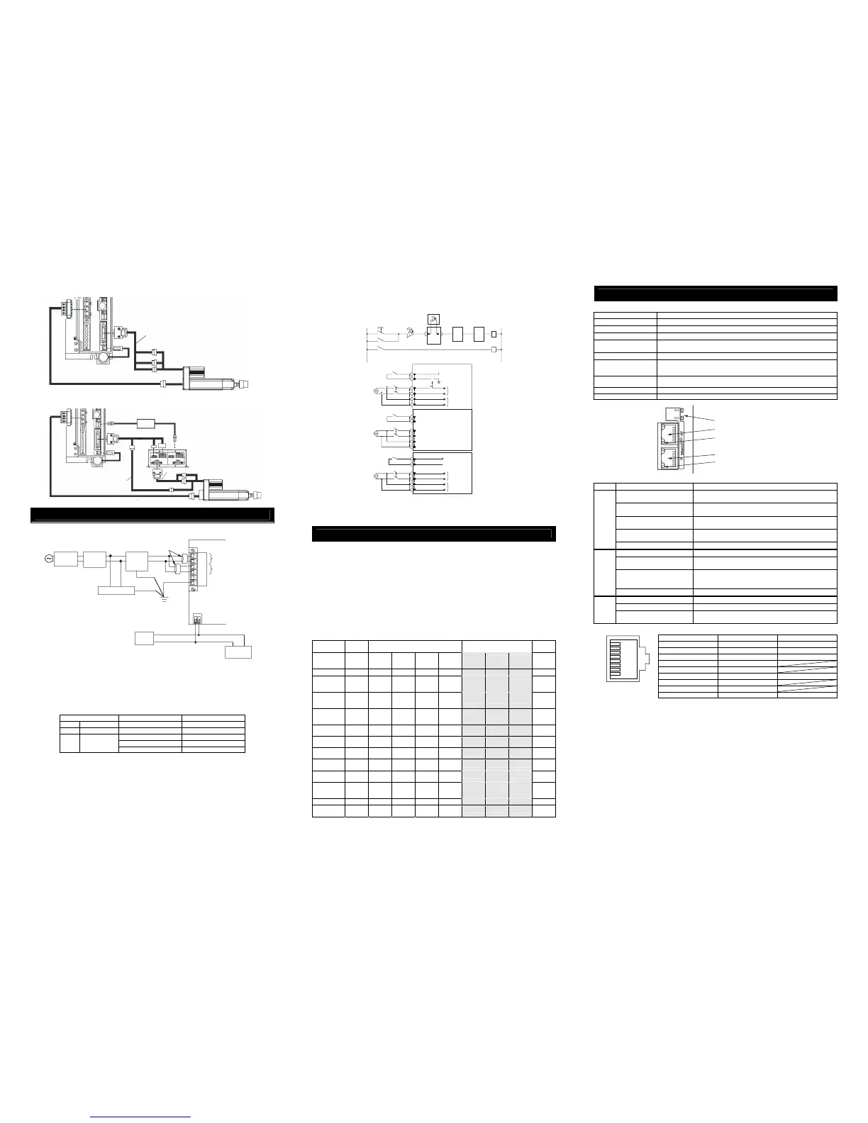
Connector RJ45 Connector × 2pcs (Input × 1, Output × 1)
Connection Daisy chain only
● Interface Section
● Status LED Displays of EtherCAT® Type
Name Indication Color Description
OFF
Initial condition (EtherCAT® communication in “INIT”
condition) or the power is OFF
GN (Illuminating)
In normal operation (EtherCAT® communication in
“OPERATION” condition)
GN (Flashing)
(ON:200ms/OFF:200ms)
(EtherCAT® communication in “PRE-OPERATION” condition)
GN (Flashing)
(ON:200ms/OFF:1000ms)
(EtherCAT® communication in “SAFE-OPERATION” condition)
RUN
OR (Illuminating) Communication component (module) error
OFF No abnormality or the power is OFF
OR (Flashing)
(ON:200ms/OFF:200ms)
Construction information (settings) error
(Information received from the master cannot be set)
OR (Flashing)
(ON:200ms × 2 times
/OFF:1000ms)
Communication section circuit error
(Watchdog timer timeout)
ERR
OR (Illuminating) Communication component (module) error
OFF Link status not detected or the power is OFF
GN (Illuminating) Linked (No network congestion)
Link/
Activity
GN (Flashing)
(ON:50ms/OFF:50ms)
Linked (Network in congestion)
● EtherCAT® Connector
Pin No. Signal Name Abbreviated Code
1
Data sending + TD+
2
Data sending − TD−
3
Data receiving + RD+
4 Not used
5 Not used
6
Data receiving − RD−
7 Not used
8 Not used
Connector Hood Security grounding FG
● Operation Mode Setting and Address Allocation
The operation mode is set using the parameters.
Set the mode change switch on the controller front panel to “MANU” side and set the parameter No. 84
“FMOD: Field Bus Operation Mode” using the teaching tool such as PC software for RC.
[Refer to the Instruction Manual for the details]
● Node address setting
The node address is set using specific parameters.
Set the parameter No. 85 “NADR: Field Bus Node Address”using the teaching tool such as PC software
for RC.
Settable Range : 0 to 127 (It is set to 17 which is the I/O slave top address of EtherCAT® at the delivery.)
● Communication Speed Setting
It is not necessary to do any settings because it automatically follows the communication settings applied
to the master for the communication frequency.
(Note) After parameter setting, reset the controller mode change witch to “AUTO” side, and then cycle the
controller power.
CB-RCS2-PLLA
RCS2-RA13R
(with Loadcel)
Absolute Battery
(for Absolute Type)
Status LED (RUN/ERR)
EtherCAT® Output Port
Link/Activity LED (Output)
EtherCAT® Input Port
Link/Activity LED (Input)
CB-LDC-CTL□□□-JY
CB-RCS2-PLLA
RCS2-RA13R
(with Loadcell and Brake)
CB-RCS2-PLA (enclosed to Brake Box)
24V DC
Brake Box
RCB-110-RA13-0
Connect to back side
Absolute Battery
(for Absolute Type)
Power Supply for Brake
1
8
RJ45 8-pin
Modular Connector
(Controller Side)
24V
Emergency stop
reset switch
Emergency stop
switch
Emergency stop switch
for the teaching pendant
(Note 1)
SCON
First unit
SCON
Second
unit
SCON
Nth unit
S1 S2 S1 S2 S1 S2
CR1
(Note 1)
0V
MC1
CR1
CR1
CR1
(Note 1)
MC1
(Note 2)
AC100V
AC200V
SCON-CA/CAL
SCON-CGAL
EMG+
EMG-
L1
L2
L1C
L2C
24V
Motor power cutoff relay
Motor
power supply
Control
power supply
CR1
(Note 1)
MC1
(Note 2)
AC100V
AC200V
EMG+
EMG-
L1
L2
L1C
L2C
SCON-CA/CAL
Second unit
EMG-
EMG+
CR1
(Note 1)
24V
MC1
(Note 2)
AC100V
AC200V
L1
L2
L1C
L2C
Motor
power supply
Control
power supply

 Loading...


