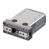
Do you have a question about the IAI RCP6 Series and is the answer not in the manual?
Defines IAI's pulse press technology, combining stepper motor and load cell for power control.
Highlights the actuator's ability to perform both pushing and pulling operations without time limitations.
Emphasizes the reduced cost compared to IAI servo presses due to the pulse motor.
Details the available models based on push force, ranging from 60N to 2000N.
Demonstrates the user interface for setting up actuator positions and operations.
Illustrates a practical application of the easy setup process for a specific task.
Details the RCP6 series, RRA types, and battery-less absolute encoder specifications.
Covers motor types, lead screw specifications, and available stroke lengths for actuator models.
Lists compatible controllers, cable length options, and additional features like brakes and flanges.
Presents a table summarizing key specifications like stroke, lead, max force, payload, and reference pages.
Detailed breakdown of key parameters for the RCP6-RRA4R model, including lead, payload, and force capabilities.
Important notes on selection criteria, operational limits, and compliance with overseas standards.
Details the function of the brake option and how to change the motor-encoder cable exit direction.
Explains the use of flange brackets for mounting and information on foot brackets for top mounting.
Covers options for installing a load cell and specifying motor side-mounted direction.
Provides detailed diagrams of actuator dimensions, mounting holes, and cable connections.
Tables detailing dimensions, mass, and weight based on actuator stroke length.
Lists controllers compatible with the actuators and their operational methods.
Key parameters for the RCP6-RRA6R model, including lead, payload, speed, and force capabilities.
Important notes on selection and adherence to overseas standards for the RRA6R model.
Lists available options like Brake, Cable exit direction, Flange, Foot bracket, Load cell, and motor mounting.
Data on payload capacity based on speed and acceleration settings for the RRA6R model.
Illustrates the relationship between stroke length and maximum speed for different operating modes.
Detailed diagrams showing dimensions, mounting points, and cable connections for the RRA7R model.
Tables for RRA7R, listing dimensions, mass, and weight as a function of stroke length.
Identifies compatible controllers for the RRA7R actuator and their control methods.
Key parameters for the RCP6-RRA7R model, including lead, payload, speed, and force capabilities.
Details available options and provides tables for payload by speed/acceleration and stroke/max speed.
Details available options such as Brake, Cable exit, Flange, Foot bracket, Load cell, and motor mounting.
Tables showing payload capacity relative to speed and acceleration for RRA7R models.
Charts illustrating the relationship between stroke, speed, and force command values.
Comprehensive diagrams illustrating the dimensions, mounting, and cable connections for the RRA7R model.
Tables detailing the mass of the RRA7R actuator according to its stroke length.
Enumerates the controllers that can be operated with the RRA7R actuators and their control methods.
Explains the role of the brake option and how to change the motor-encoder cable exit direction.
Provides specific model numbers and weights for flange options on RRA4R, RRA6R, and RRA7R.
Information on foot bracket options for top mounting, including model numbers and bracket counts.
Details the load cell (LCT) option and the specification for motor side-mounted direction (ML/MR).
Visual guide showing the components of the actuator system for maintenance purposes.
Lists model numbers for replacement parts like motor units, cables, and load cells.
Instructions for proper mounting orientation to ensure optimal performance and prevent issues.
Critical safety guidelines for installation and handling the load cell to prevent damage and ensure accuracy.
Highlights encoder support and the controller's capability for force control using a load cell.
Describes the N unit display feature for target loads and collision detection thresholds.
Lists available PCON-CBP/CGBP models with external views and supported network types.
Details the model specification items including series, type, encoder, I/O type, and power supply.
Describes options for PC teaching software, touch panel teaching pendants, and connection cables.
Details supplied actuator/controller cables and optional 24V power supplies and dummy plugs.
Details external input specifications, NPN, and PNP output configurations for PIO interface.
Explains the 8 types of PIO patterns and their associated modes for controlling the actuator.
Comprehensive table detailing signal assignments for the I/O flat cable across different PIO patterns.
Explains the 8 selectable operation modes for controlling the actuator via field network.
Details PLC data areas and supported functions for each operation mode and network type.
Covers key specifications like axes, voltage, current, encoder, cable length, and mass.
Details operating environment, temperature, humidity, and ingress protection ratings.
Shows external dimensions for screw and DIN rail mounting, including detailed views.
Identifies key parts of the controller, including status LEDs, connectors, switches, and power supply.
Details the TB-02 teaching pendant and PC teaching software (RCM-101) for setup and operation.
Information on optional 24V power supplies (PSA-24/PSA-24L) and the dummy plug (DP-5).
Lists compatible motor/encoder and PIO flat cables with their model names for replacement.
Provides detailed diagrams of cable wiring and pin assignments for both actuator and controller sides.
| Type | Controller |
|---|---|
| Model | RCP6 Series |
| Storage Temperature | -10 to 60°C |
| Control Method | Position Control |
| Programming | IAI Software |
| Communication Interface | RS-232C, Ethernet |
| Humidity | 85% RH or less (non-condensing) |


