RCP6 RoboCylinder
7 RCP6-RRA4R
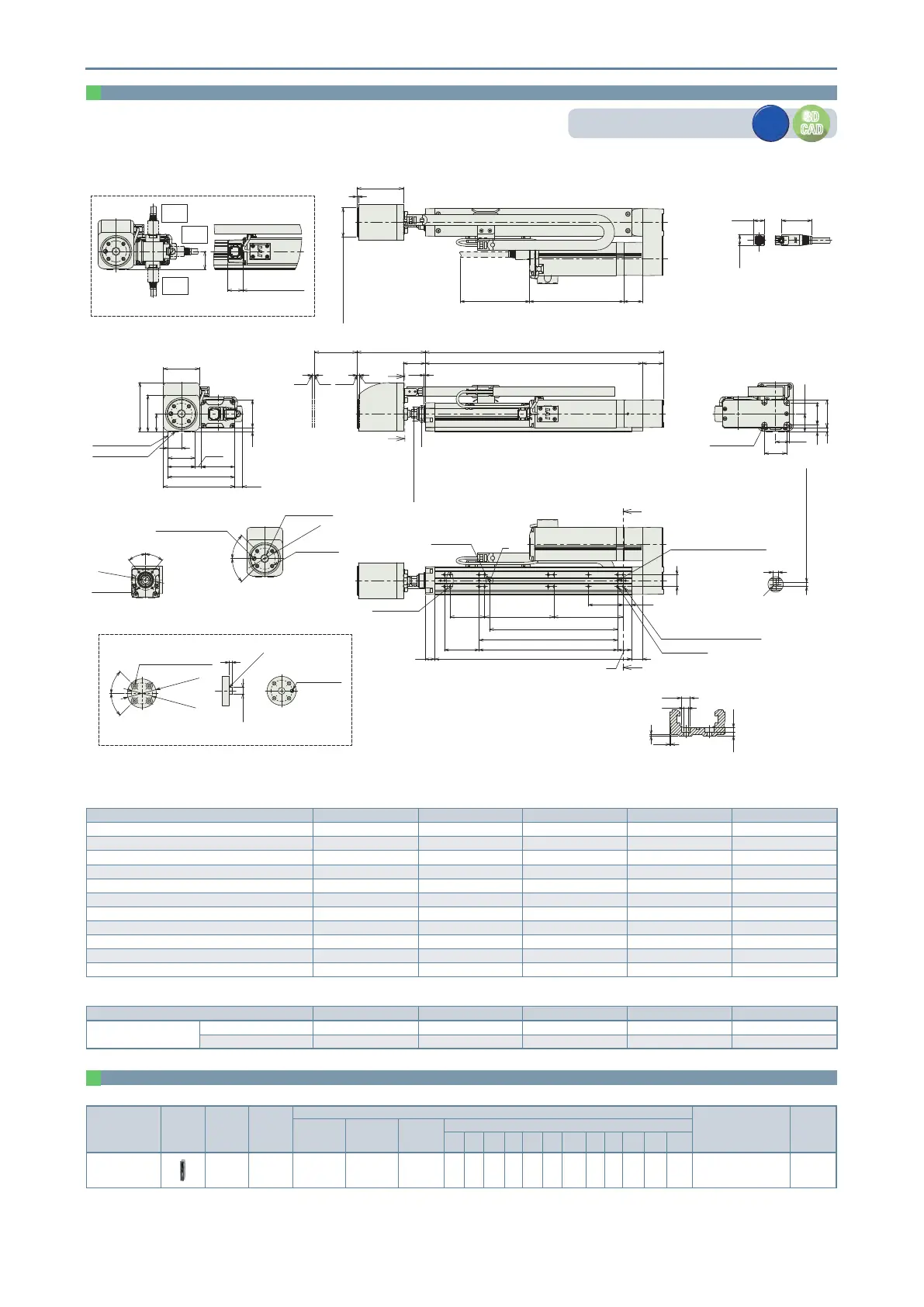
*1 The 2 counterbored mounting holes shown in the gure cannot be used.
(Note) When returning to the home position, the rod will move to the M.E. Be careful of interference with surrounding objects.
ST: Stroke
M.E: Mechanical end
S.E: Stroke end
S
S
V
V
Load cell tip mounting jig reference size
4 4
ST
30
A
L
98.5
31.5
1.5
ø24h7
ø20 (rod outer diameter)
S.E.M.E.
Home
M.E.
01 23
32
40
6
4-M4 depth 9
(20)
(26)
39
40
97
(6)
40
48
(8.7)
52
71
103
26
19.5
(11)
53
Base mounting surface
Reference surface
(Dimension B range)
20
C
B 16
17
K (between ø3 hole - ø3 hole)
J (ø3 hole - oblong hole)
2-ø3H7 reamed, depth 4
(from base mounting surface)
E-M4 depth 6
14
H-
ø
3.4 through,
6.5 deep counterbored,
depth 3.5 (from the opposite side)
G×100P
1250
50 F
D×100P
Oblong hole
*1 Unavailable
P
40°
40°
P.C.D.30
4-M4 depth 8
Cross section of S-S
45°
45°
ø5H7 reamed, depth 5
ø10H7 depth 5
P.C.D.30.5
4-M5 depth 8
Jig mounting dimensions details
(equidistant)
4
Depth 4 from base seating surface
(R)
Detailed view of P
Base oblong hole details
(43.3)
Cable connection
(16.2)
(15.6)
Cable exit direction (option)
22
135 (w/o brake)
179 (with brake)
P.C.D.30.5
ø42 or more
45°
45°
4-ø5.5 through,
ø9.5 deep counterbored,
depth 5.5
(equidistant)
4
ø10h7
R0.5 or less
ø5H7 reamed
3
+0.010
0
Must be
100 or more
2
ø42 (load cell outer diameter)
136 (w/o brake)
180 (with brake)
27
67
26
Cable exit direction (option)
CJB
bottom
CJO
outside
CJT
top
0.5
1
2.5 3.5
ø3.4
ø6.5
Cross section V-V
Details of base mounting counterbored holes
Dimensions by stroke
Stroke 110 160 210 260 310
L 244 294 344 394 444
A 214 264 314 364 414
B 184 234 284 334 384
C 50 100 50 100 50
D 1 1 2 2 3
E 6 6 8 8 10
F 100 50 100 50 100
G 0 1 1 2 2
H 8 10 10 12 12
J 85 85 185 185 285
K 100 100 200 200 300
Mass by stroke
Stroke 110 160 210 260 310
Mass
(kg)
Without brake 2.2 2.3 2.4 2.6 2.7
With brake 2.4 2.5 2.7 2.8 2.9
Dimensions
CAD drawings can be downloaded from our website.
www.robocylinder.de
3D
CAD
3D
CAD
2D
CAD
2D
CAD
Applicable Controllers
The actuators on this page can be operated by the controllers indicated below. Please select the type depending on your intended use.
Name
External
view
Maximum
number of
connectable
axes
Power
supply
voltage
Control method
Maximum number
of positioning points
Reference
page
Positioner
Pulse-train
Program
Network (*Option)
DV CC CIE PR CN
ML
ML3
EC EP
PRT
SSN
ECM
PCON-CBP/
CGBP
1 24VDC
*Option
- -
---
- -
512
(768 for network
spec.)
18
(Note) Please refer to P. 19 for information on network abbreviation codes such as DV and CC.
 Loading...


