RCP6 RoboCylinder
RCP6-RRA6R 10
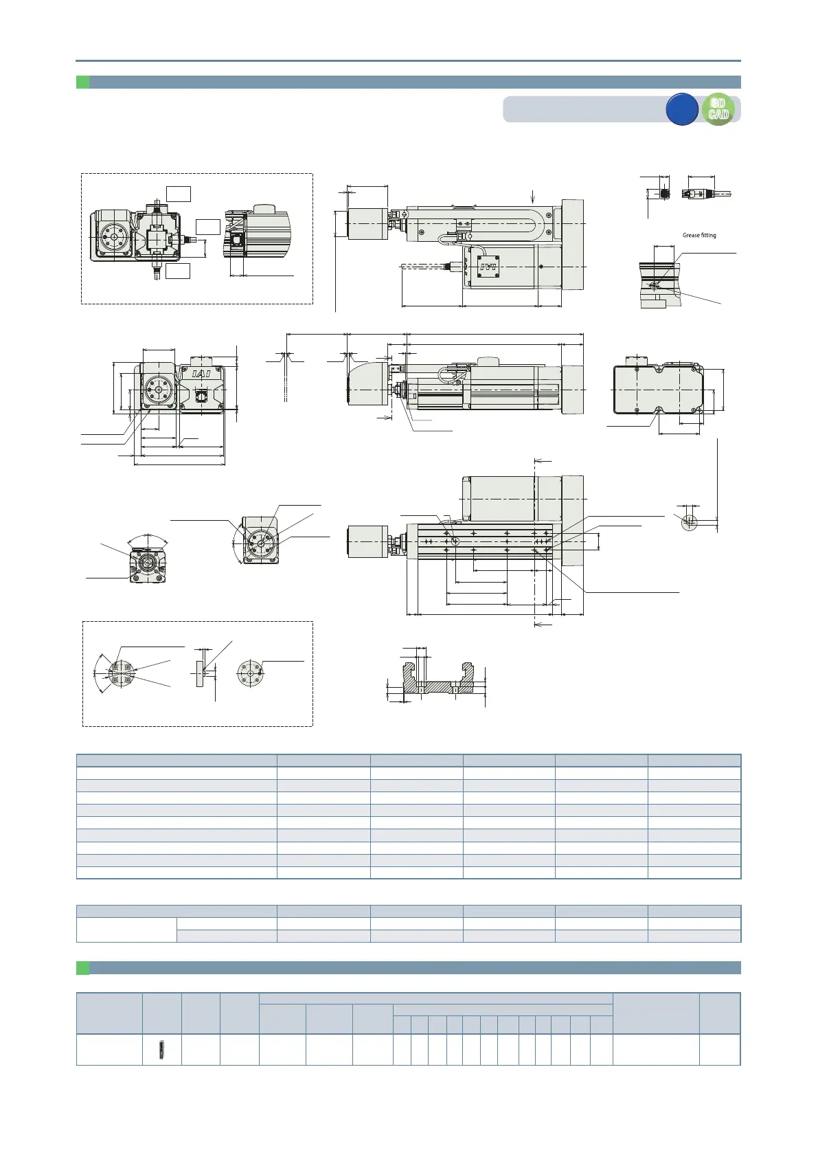
Dimensions
CAD drawings can be downloaded from our website.
www.robocylinder.de
3D
CAD
3D
CAD
2D
CAD
2D
CAD
Applicable Controllers
The actuators on this page can be operated by the controllers indicated below. Please select the type depending on your intended use.
Name
External
view
Maximum
number of
connectable
axes
Power
supply
voltage
Control method
Maximum number
of positioning points
Reference
page
Positioner
Pulse-train
Program
Network (*Option)
DV CC CIE PR CN
ML
ML3
EC EP
PRT
SSN
ECM
PCON-CBP/
CGBP
1 24VDC
*Option
- -
---
- -
512
(768 for network
spec.)
18
(Note) Please refer to P. 19 for information on network abbreviation codes such as DV and CC.
ST: Stroke
M.E: Mechanical end
S.E: Stroke end
(Note) When returning to the home position, the rod will move to the M.E. Be careful of interference with surrounding objects.
S
S
W
W
3 3
ST
36
A
L
98.5
31.5
2
ø25 (rod O.D.)
ø30h7
M.E.
Home
S.E.
M.E.
67
67
4-M6 depth 14
(40)
(40)
149
73
70(1)
136
(11)
58
57
7
(5.1)
28.5
52
33
85
60
16
Base mounting surface
Reference surface
(Dimension B range)
18
3-ø4 H7 reamed, depth 5.5
(from base mounting surface)
E-M5 depth 10
K (ø4 hole - ø4 hole)
D×100P
65
10
15
B
28
H-ø4.5 through,
ø8 deep counterbored, depth 4.5
(from the opposite side)
30G×100P
J
(ø4 hole - oblong hole)
Oblong hole
P
45°
45°
P.C.D.40
4-M6 depth 12
Cross section of S-S
(equidistant)
Depth 5.5
from base mounting surface
(R)
5
Detailed view of P
Base oblong hole details
45°
45°
ø5H7 reamed, depth 5
ø10H7 depth 5
P.C.D.30.5
4-M5 depth 8
Jig mounting dimensions details
(equidistant)
ø3.5
port diameter
32.5
for ball screw/guide
(same on opposite side)
Arrow view V
Greasing port
(43.3)
Cable connection
(16.2)
(15.6)
117 (w/o brake)
157 (with brake)22
ø42 or more
P.C.D.30.5
45°
45°
4-ø5.5 through,
ø9.5 deep counterbored,
depth 5.5
Load cell tip mounting jig reference size
(equidistant)
4
R0.5 or less
ø10h7
ø5H7 reamed
4
+0.012
0
(36)
Must be 100 or more
2
38.5
ø42 (load cell outer diameter)
67
125 (w/o brake)
165 (with brake)
V
28.5
CJO
outside
Cable exit direction (option)
CJB
bottom
CJT
top
ø8
ø4.5
5
0.5
5.5
4.5
Cross section of W-W
Details of base mounting counterbored holes
Dimensions by stroke
Stroke 115 165 215 265 315
L 291 341 391 441 491
A 255 305 355 405 455
B 222 272 322 372 422
D 1 1 2 2 3
E 6 6 8 8 10
G 1 2 2 3 3
H 4 6 6 8 8
J 85 85 185 185 285
K 100 100 200 200 300
Mass by stroke
Stroke 115 165 215 265 315
Mass
(kg)
Without brake 4.0 4.2 4.5 4.7 4.9
With brake 4.2 4.4 4.6 4.9 5.1
 Loading...


