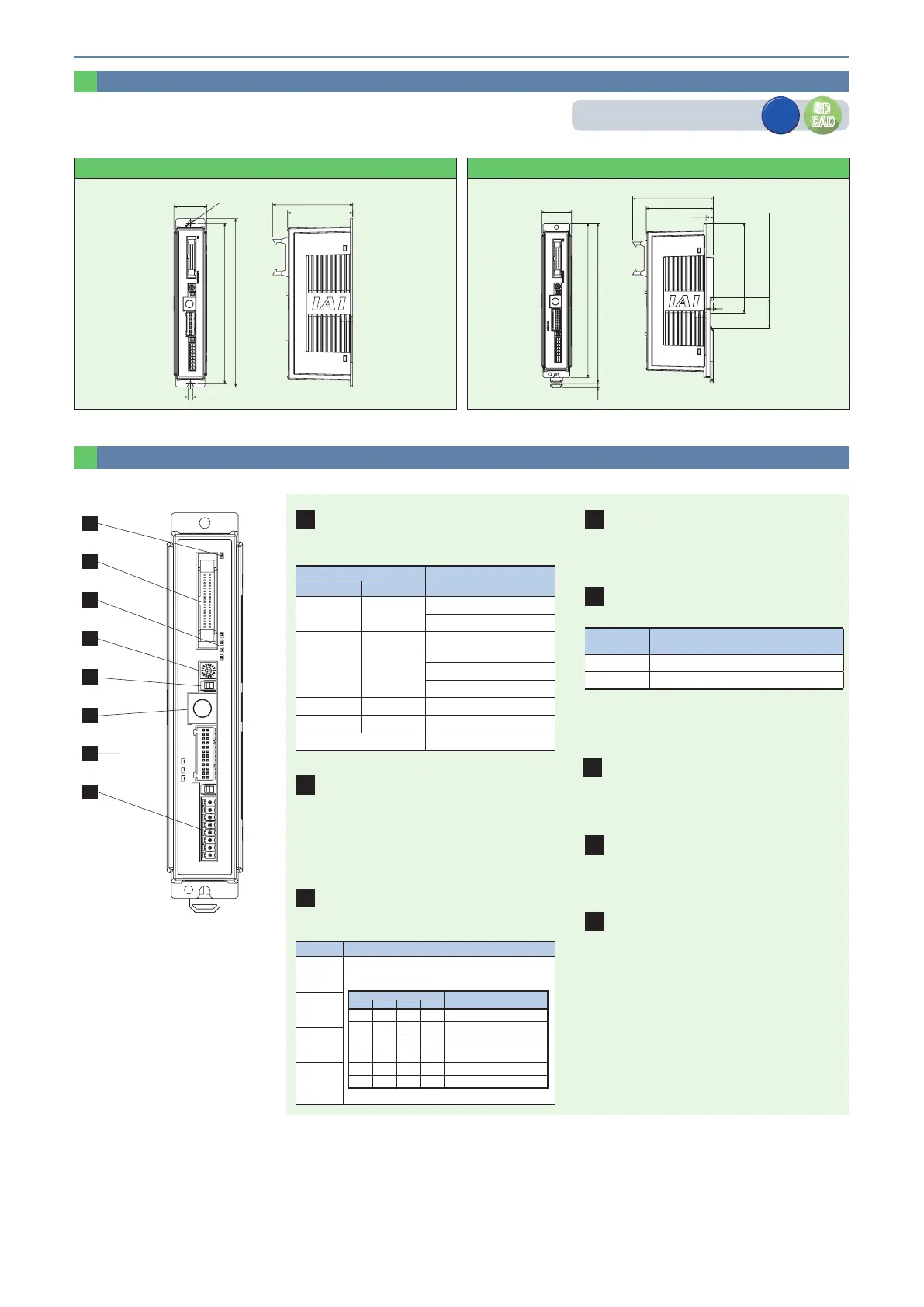
External Dimensions
Part Names
1
2
3
4
5
6
7
8
2
PIO connector /eld network connector
Cable connector for performing parallel communication with
peripheral devices such as PLC.
6
SIO connector
Connector for touch panel teaching pendant or PC
communication connection.
7
Motor/encoder connector
Connector to connect an actuator motor and encoder cable.
8
Power supply connector
Connector for power supply and emergency stop status signal
input.
4
Axis number setting switch
Used to set an address to identify each controller, when
controllers are linked.
1
Controller display status LED
Indicates the status of the controller.
: ON, −: OFF,
: Blinking
LED
Operating status
SV (green) ALM (red)
− −
Control power OFF
Servo OFF
−
Alarm
(operation cancel level or above)
Motor drive power supply
Emergency stop
− Servo ON
− AUTO servo OFF
(orange)
Initialized when power is turned ON
3
Current/alarm monitor LED
Displays the normal command current ratio. Displays the
alarm code when an alarm occurs.
LED Operating status
STS3 (green)
Status display
• Servo ON: Displays the current command current ratio
(proportion of rated value).
STATUS
Command current ratio
3 2 1 0
ALM8 ALM4 ALM2 ALM1 Simple alarm code
– – – – 0.00% ~ 6.24%
– – –
6.25% ~ 24.99%
– –
25.00% ~ 49.99%
–
50.00% ~ 74.99%
75.00% ~ 100.00% or higher
•During alarm: Displays a simple alarm code.
STS2 (green)
STS1 (green)
STS0 (green)
5
Operation mode setting switch
Switch for the interlock.
Name Description
MANU Commands from PIO are not received
AUTO Commands from PIO can be received
* The emergency stop switch on the touch panel teaching pendant is enabled
when the connection is made, regardless of the status (AUTO or MANU). Be
sure to turn the power OFF when disconnecting the touch panel teaching
pendant and SIO communication cable.
<PCON-CBP/CGBP>
178.5
170.5
35
5
84.8
69.6
ø5
35
(5)
93.3
78.1
8.5
4
DIN rail
104 from center
35.4
(35mm DIN rail width)
185
178.5
Screw mounting specication DIN rail mounting specication
CAD drawings can be downloaded from our website.
www.intelligentactuator.de
3D
CAD
3D
CAD
2D
CAD
2D
CAD
25 PCON-CBP
PCON- CBP Controller
 Loading...


