Options
a
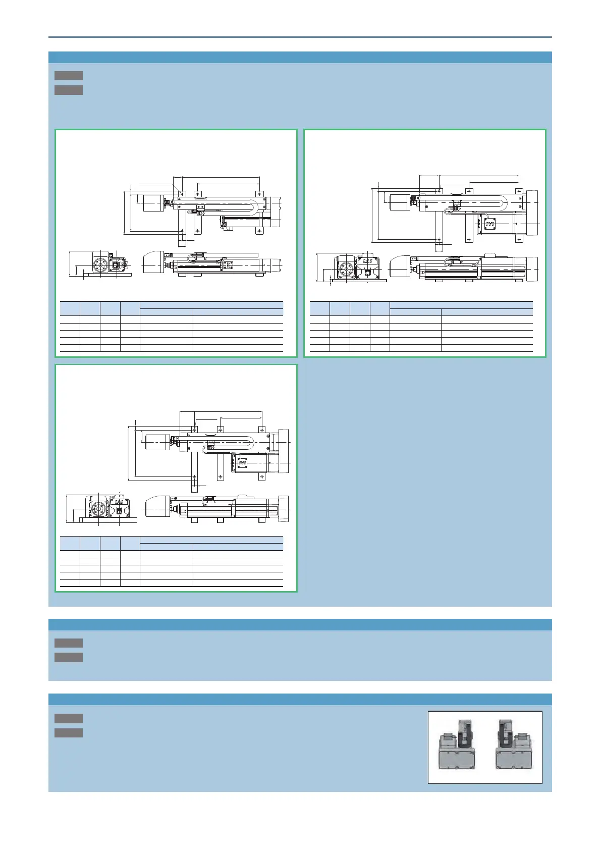
Foot bracket
This bracket is used for mounting the actuator body from the top with bolts.
The actuator body may be twisted or deformed if an insucient number of mounting foot brackets are used. Actuator life
could also be shortened.
* Refer to the installation dimensions in the actuator drawing for the installation pitch between the foot brackets.
Description
Model
FT
9
42
96
180
37
H
10160
J-ø6.6 through
25
12.5
RCP6-RRA6R
Individual model number: RCS3-FT-RA6-2
(Note 1)
140
120
H
J-ø6.6 through
30
10
25
12.5
35
9
80
RCP6-RRA4R
Individual model number: RCS3-FT-RA4-2
(Note 1)
ST G H J
"FT" selected as option
No. of foot brackets
Number of hex socket bolts enclosed
110 150 0 4 2 4
160 200 0 4 2 4
210 250 200 6 3 6
260 300 200 6 3 6
310 350 200 6 3 6
ST G H J
"FT" selected as option
No. of foot brackets
Number of hex socket bolts enclosed
115 165 0 4 2 4
165 165 0 4 2 4
215 265 165 6 3 6
265 265 165 6 3 6
315 365 165 6 3 6
210
180
25
12.5
15
J-ø9 through
G
H
47
56
19
52
RCP6-RRA7R
Individual model number: RCS3-FT-RA7-2
(Note 1)
(Note 1) 2 hex socket bolts enclosed
Equipped with load cell
This option installs a load cell to the rod tip and operates with force control.
*LCT must be selected for pulse press.
Description
Model
LCT
ST G H J
"FT" selected as option
No. of foot brackets
Number of hex socket bolts enclosed
120 160 0 4 2 4
170 160 0 4 2 4
220 260 160 6 3 6
270 260 160 6 3 6
320 360 160 6 3 6
Motor side-mounted direction
Description
This code is for specifying the motor side-mounted direction.
Side-mounted to left is ML and right is MR.
Model
ML / MR
Side-mounted to left (ML) Side-mounted to right (MR)
15 Options
 Loading...


