Options
* Please check the Options reference pages to conrm each option.
Name
Option code
Reference page
Brake B 14
Cable exit direction (bottom) (Note 1) CJB 14
Cable exit direction (outside) CJO 14
Cable exit direction (top) CJT 14
Flange (front) FL 14
Foot bracket (Note 1, 2) FT 15
Equipped with load cell (standard equipment) (Note 3) LCT 15
Motor side-mounted (left) (Note 4) ML 15
Motor side-mounted (right) (Note 4) MR 15
(Note 1) Foot bracket (FT) cannot be selected when selecting cable exit direction (bottom)
(CJB).
(Note 2) Please refer to P. 15 for the number of brackets included.
(Note 3) Be sure to enter a selection in the options section of the model number.
(Note 4) Be sure to enter a code in the options section of the model number.
Cable Length
Type Cable code
Standard type
P (1m)
S (3m)
M (5m)
Specied length
X06 (6m) ~ X10 (10m)
X11 (11m) ~ X15 (15m)
X16 (16m) ~ X20 (20m)
Robot cable
R01 (1m) ~ R03 (3m)
R04 (4m) ~ R05 (5m)
R06 (6m) ~ R10 (10m)
R11 (11m) ~ R15 (15m)
R16 (16m) ~ R20 (20m)
RCP6 RoboCylinder
Tables of Payload by Speed/Acceleration
High-output setting enabled
(the unit for payload is kg)
High-output setting disabled
(the unit for payload is kg)
Stroke and Max Speed
High-output
setting
Stroke (mm)
115 165 215 265 315
Enabled 110
Disabled 80
(Unit: mm/s)
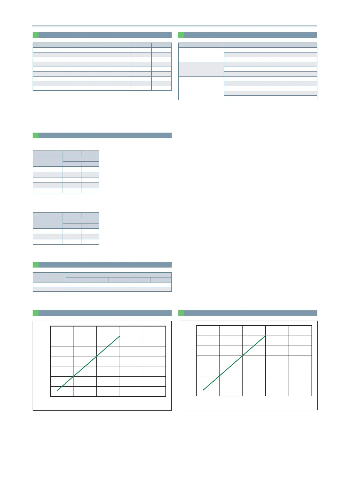
Correlation diagram between push force and push command value
Correlation diagram between pull force and pull command value
9 RCP6-RRA6R
Orientation Horizontal Vertical
Speed
(mm/s)
Acceleration (G)
0.3 0.3
0 10 10
35 10 10
70 10 10
100 10 10
110 10 10
Orientation Horizontal Vertical
Speed
(mm/s)
Acceleration (G)
0.3 0.3
0 10 10
35 10 10
80 10 10
0 20 40 60 80 100
0
100
200
300
400
500
600
700
0 20 40 60 80 100
Pull command value (%)
0
100
200
300
400
500
600
 Loading...


