26 | Unpacking and Installation | KermaX-plus
®
Chamber
CAUTION
DO NOT EXCEED THE ACTIVE AREA OF THE CHAMBER
The size of the radiation field at the surface of the centered chamber may not
exceed the active area of the chamber (see Chapter 9, Technical Specifications).
IMPORTANT NOTICE
REFERENCE DIRECTION OF INICIDENT RADATION
The central beam direction of incident radiation must be orthogonal to the
Chamber surface.
CAUTION
DO NOT USE DAMAGED KERMAX® PLUS PARTS
Do not use damaged parts.
4.2.2. Electrical Configuration of KermaX-plus
®
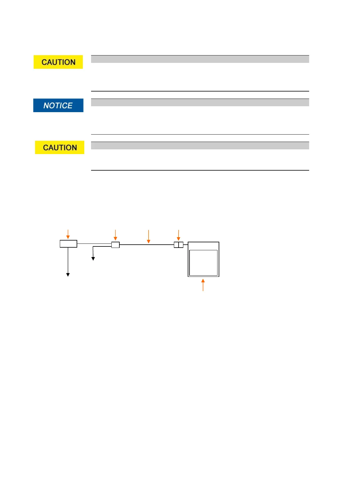
Configuration of the KermaX-plus
®
measuring system consists of the following minimum components:
The setup procedure:
1. Connect chamber cable to the AKP cable connections with the help of the modular connector plug
and the Y-connector.
2. Connect the power pack to the Y-connector of the AKP cable.
3. Connect the Interface [counter/display] to the Y-connector of the AKP cable.
4. Connect the power supply to the mains. Make sure that the power supply is appropriate for medical
Equipment and accordingly UL resp. IEC 60601 certified (see Chap. 2.5.1).


 To Next Page