1-7
INSTALLATION
DC SERIES BOILERS / WATER HEATERS DC 15-95, DC 15-96, DC 20-125, DC 33-160
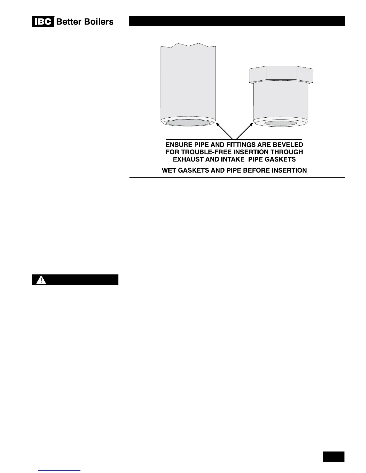
Exhaust piping is inserted directly into the 3" female stainless steel tting on the
top, left side of the boiler / water heater and run horizontally or vertically to the
outdoors. Bird screen of 1/4" stainless steel or plastic mesh (eg. IPEX System
636 drain grate for CPVC systems) is useful to guard against foreign objects.
Follow all installation instructions supplied by the pipe and tting
manufacturer.
Ensure all venting components are clean of burrs/debris prior to assembly.
Care is to be taken to avoid ingestion into the fan of PVC/ABS debris left in the
combustion air piping.
All joints must be secured using appropriate solvent cement to bond the
respective pipe material (Canada: CPVC cement approved under ULC-S636,
in accordance with its manufacturer instructions; USA: PVC (ASTM D2564),
or PVC/ABS (D2235) - Use transition glue anywhere that PVC and CPVC are
joined. Follow the cement manufacturer’s instructions closely when joining
various components. For PPs, connections shall be secured using approved
retainer clips supplied by the respective PPs manufacturer.
All vent connections must be liquid and pressure tight. Prior to ring the boiler,
and before any of the venting run is concealed by the building construction, the
installer must test the exhaust joints under fan pressure with the vent blocked,
using a soap/water solution. Installer must ll condensate trap prior to test.
1.4.4 Venting Passage Through Ceiling and Floor
•
Conrm material meets local codes including re stopping requirements.
• Some local jurisdictions require a minimum initial length of pipe be exposed or
accessible for inspection.
• Pipe clearances - no IBC requirements, but best practice allows a minimum
1/4" gap around the pipe to prevent binding and expansion noise; follow local
codes.
• All piping must be liquid and pressure tight.
BEST PRACTICES
To reduce the possibility of
expansion noise, allow a 1/4"
gap around the exhaust and
air intake piping.
Figure 4