3.10.2.2 Boiler pump
The boiler (primary) pump is powered by the yellow wire from the pair labeled "Boiler Pump". Wire the
pump's neutral to the white wire labeled "AC In". Do not attempt to connect the boiler pump to the pump/zone
valve terminal block along the controller’s right edge as this is reserved for the secondary pumps and/or zone
valves only.
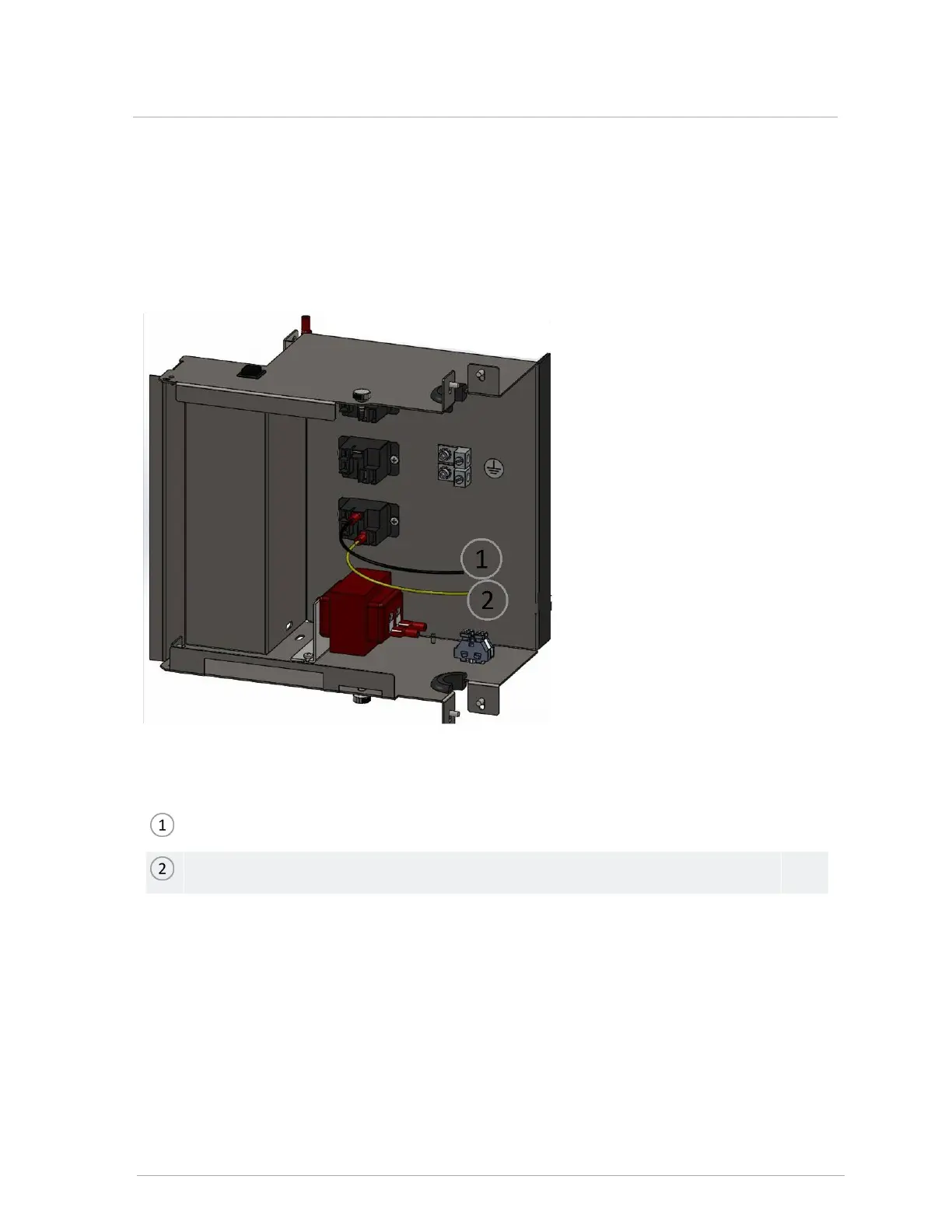
Figure 34 Electrical box with boiler pump relay - black and yellow wires
Power in - black wire.
To boiler - yellow wire.
If the total boiler amperage drawn is less than 12 amps and the boiler pump is 120V, you can connect the
black wire from the relay to the line voltage mains supplied to the boiler. For 120 volt boiler pumps, the black
wire can be connected to the line voltage mains and the yellow wire connected to boiler pump. For 208/240
volt boiler pumps, the black wire can be one leg of the 208/240 voltage mains and the yellow wire connected
to the boiler pump. The boiler pump relay may require connection to a second electrical circuit (amperage
greater than 4 amps). The boiler pump relay is rated for a maximum amperage load of ¾ horsepower. A
disconnect switch should be installed to isolate the boiler pump and the boiler pump relay power supply.
3.10.2 120VAC line-voltage hook-up
 Loading...