Pumps can be switched on/off using the touchscreen controller, so there is no need for temporary pump
wiring during system filling / air purging. If pumps are hard-wired to the panel during the system fill/purge
phase, re-wire the boiler pump to the primary pump leads inside the wiring box so the primary pump
purge function is active.
In a new construction application, use a construction thermostat, or jumper with an in-line on/off switch –
for on/off management of the boiler. Do not just turn off power from the unit, or its moisture management
routine will be interrupted (fan turns at ultra low rpm for 90 minutes after burner shutdown). Treat it like a
computer, where you do not just pull the plug when done. If a "low airflow / check vent" error signal
shows, check for (and remove) any water in the clear vinyl air reference tubes. This has been seen
occasionally at construction sites where the boiler has been repeatedly de-powered wet.
The combined current of all load pumps connected through the on-board pump relays should not exceed
10 amps. The control circuit board is protected using on-board field replaceable fuses. Each pump is
fused with a separate 5 Amp fuse. The Alarm contact is fused with a 5 Amp fuse and the 24VAC boiler
control circuit is protected with a 2 Amp fuse.
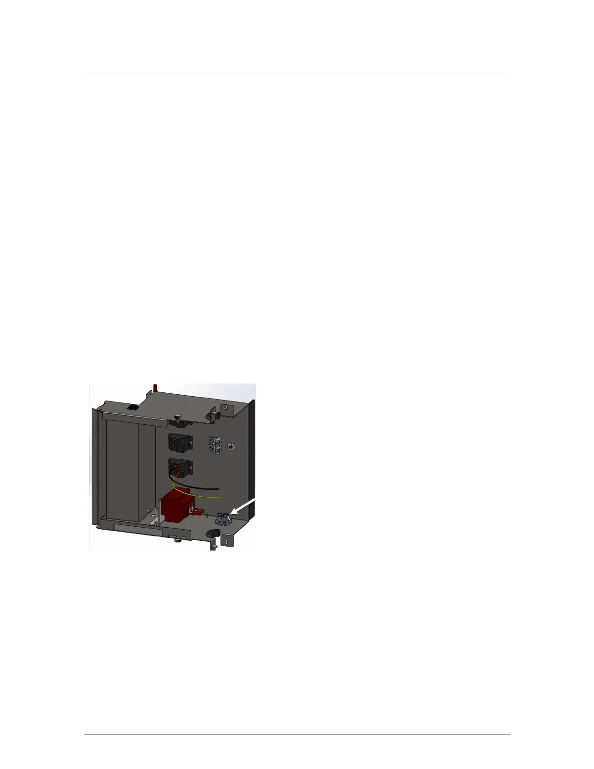
3.10.2.3 Variable speed boiler pumps
Variable speed boiler pumps are for connecting and managing speed in pumps that accept 0-10VDC on
4-20 mA input signal.
Figure 35 Electrical box with new variable speed connection
 Loading...