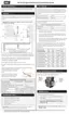
Gas valve electrical connector
Gas valve outlet: Unscrew the four (4) bolts of the flange to separate gas valve from the gas
valve. Keep gasket and bolts for re-assembly.
Figure 38 Accessing the gas valve - EX 700, 850
1. Turn off the electric power and gas supply to the boiler.
2. Ensure that the boiler cools down to the surrounding temperature. Do not drain the boiler unless
freezing conditions are expected during this procedure.
3. Remove the front cover, and then remove the boiler's top panel by removing the four Torx head
screws on the top panel of the boiler.
4. A ladder or step may be required to have a clear vertical view of the work area. Do not attempt to
reach from the front without a clear view, as damage to connectors, screws or refractory may occur.
5. Remove the screw and pull off the electrical connector from the gas valve, and disconnect the three-
(3) wire Molex plug from the the gas pressure switches.
6. Unscrew the four (4) bolts of the flange to separate the gas valve inlet from the gas line. Keep gasket
and bolts for re-assembly. (See lon Figure 38 .)
7. Unscrew the four (4) bolts of the flange to separate the gas valve outlet from the gas line. Keep gasket
and bolts for re-assembly. (See o on Figure 38 .)
8. Re-install the components in reverse order of the steps above.
9. Tune the gas valve. For instructions, see Adjusting the gas valve on page 1.
6.3.2 Replacing the gas valve
 Loading...