EasyManuals Logo

IBC EX Series Installation And Operating Manual

IBC EX Series
104 pages
To Next Page IconTo Next Page
To Previous Page IconTo Previous Page
Page #99 background imageLoading...
Page #99 background image
Boiler parts diagram
Item
Number
Description Part Number Replacement Kit Numbers
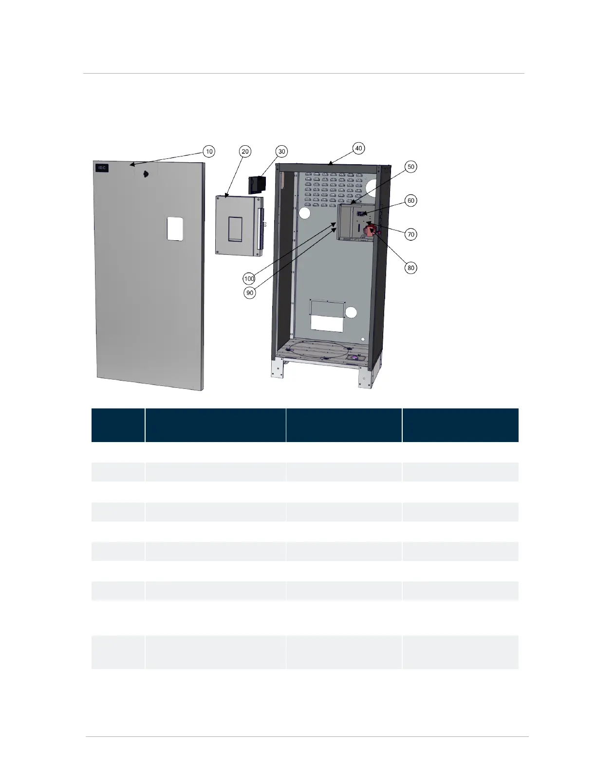
10 Door 500-134 P-1209
20 Controller 500-044 P-242
30 Safety Ignition Module 500-105 P-270
40 Top panel 251-030 P-1227
50 Controller module chassis 251-042 P-1228
60 Gas valve relay 240-165 P-1233
70 Boiler pump relay 240-165 P-1233
80 Transformer 240-008 P-9059
90 Air pressure sensor (behind
controller)
240-162 P-1210
100 Vessel high limit switch (behind
controller)
240-030 P-9070
Boiler parts diagram

Table of Contents

Other manuals for IBC EX Series

Questions and Answers:

Question and Answer IconNeed help?

Do you have a question about the IBC EX Series and is the answer not in the manual?

IBC EX Series Specifications

General IconGeneral
BrandIBC
ModelEX Series
CategoryBoiler
LanguageEnglish

Related product manuals