INSTALLATION AND OPERATION INSTRUCTIONS
1-24
HC SERIES BOILERS HC 13-50, HC 23-84, HC 29-106, HC 20-125, HC 33-160
MULTIPLE BOILER PIPING - BENEFITS AND INSTALLATION RULES
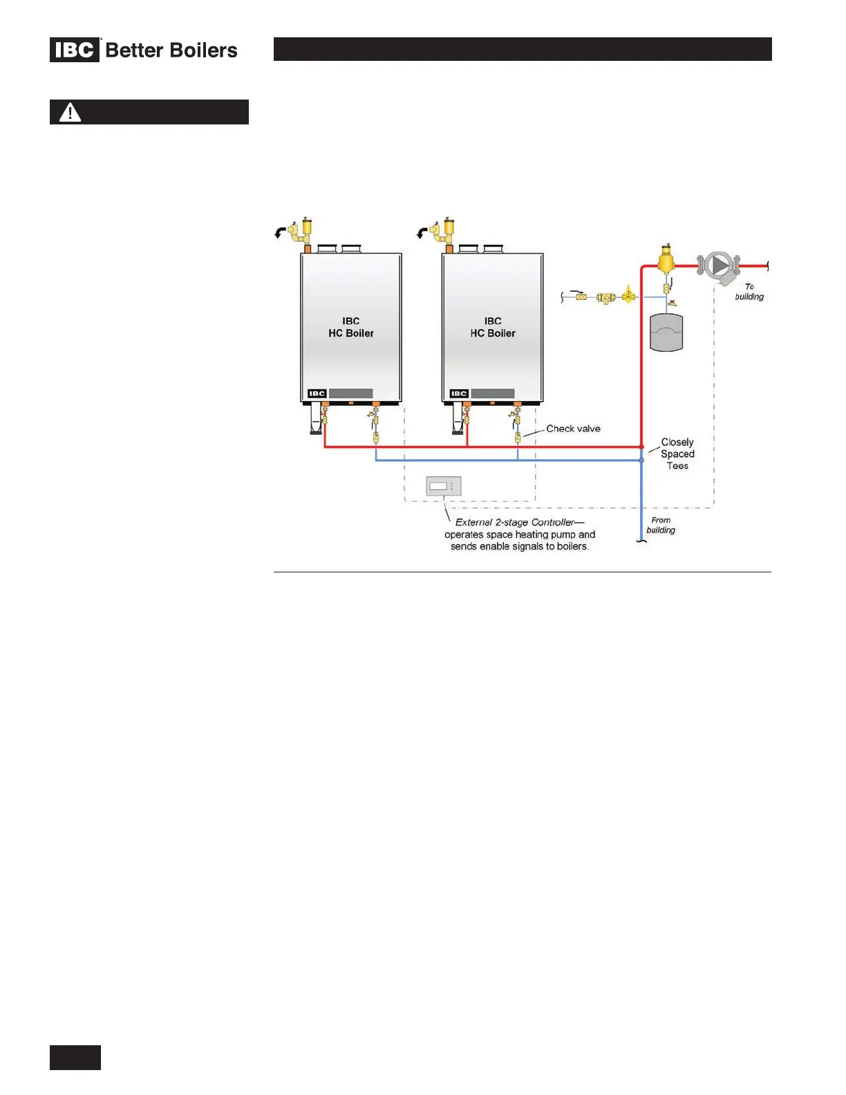
Multiple IBC HC Series boilers can be installed in a single heating system to
provide redundancy, increased output, and greater heating plant turn-down
capabilities. Primary/Secondary piping must be employed. This approach
provides constant head and ow at each boiler, regardless of ow variations in
the main building loop.
Each boiler will control its own pump, turning it off or on when heat is required.
This approach saves electricity by reducing the pumping power required as load
conditions are reduced. A multiple boiler system can be controlled by installing
an external boiler staging controller with dry contacts for each boiler. These
controllers are available from your local heating wholesaler.
Check valves are to be used in each boilers piping to prevent reverse ow when
the boiler is off.
Figure 26: Multiple boiler piping concept – concept drawing. This drawing is only a simple
schematic guide.
NOTE
The piping drawings in this
manual are simple schematic
guides to a successful
installation. There are many
necessary components not
shown, and details such as
thermal traps are left out so
the drawings have greater
clarity. We require that
our boilers be installed by
licensed and experienced
trades people who are familiar
with the applicable local
and national codes. System
design is to be completed
by an experienced hydronic
designer or Engineer. It is
necessary to carefully read
and follow these installation
instructions along with the
application drawing that ts
your system.
 Loading...


