INSTALLATION AND OPERATION INSTRUCTIONS
1-10
VFC 15-150 - VFC 45-225 MODULATING GAS BOILERS
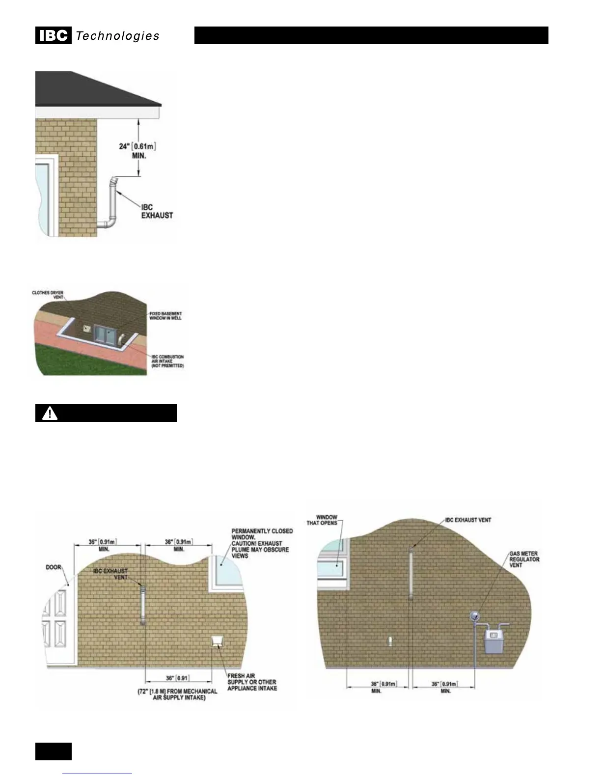
Vent terminal clearance minimums are as follows:
• Clearance above grade, veranda, porch, deck or balcony – 12" (0.3m), but
check local code also (anticipated snow levels may supersede).
• Clearance to openable window or door – 36" (0.91m) (USA – 12”)
• Verticalclearancetoventilatedsotlocatedabovetheterminalwithina
horizontal distance of 2’ (0.61m) from the centreline of the terminal.
• Clearance to each side of centreline extended above meter/regulator
assembly: - 3' (0.91m) within a height of 15' (4.6m) above the meter/regulator.
• Clearance to service regulator vent outlet: - 3' (0.91m)
• Clearance to non-mechanical air supply inlet to building or the combustion air
intake to any other appliance: - 3' (0.91m) (USA – 12" (0.3m))
• Clearance to a mechanical air supply inlet: - 6’ (1.82m) (USA - 3’ (0.91m)
above if within 10’ (3.1m) horizontally)
• Clearance above paved sidewalk or paved driveway located on public
property: - 7' (2.2m) Note: Cannot terminate directly above a paved sidewalk
or paved driveway that is located between two single family dwellings and
serves both dwellings
• Clearance under veranda, porch, deck or balcony: - 12" (0.3m). Note:
Prohibited unless fully open on a minimum of two sides below the oor.
• Ventsmustbeinstalledsuchthatuegasdoesnotdischargetowards
neighbor’s windows, or where personal injury or property damage can occur.
•
It is important to ensure proper condensate management from vent terminations.
Condensate shall not be discharged in a manner that will cause damage to
externalbuildingnishesorcomponents,orinltratethebuildingenvelope.
WARNING
In areas of high snowfall,
Users must be advised to
check side wall vent and
air intake terminations on
a regular basis to ensure
blockage does not occur.
Figure 6: Vent terminal clearances
Figure 7: Prohibited installation
Figure 9: Vent terminal clearancesFigure 8: Vent terminal clearances

 Loading...


