1-15
INSTALLATION
VFC 15-150 - VFC 45-225 MODULATING GAS BOILERS
1.5.1.1 WITH SCHEDULE 40 PLASTIC VENTING SYSTEMS
(E.G. ULC-S636 CPVC)
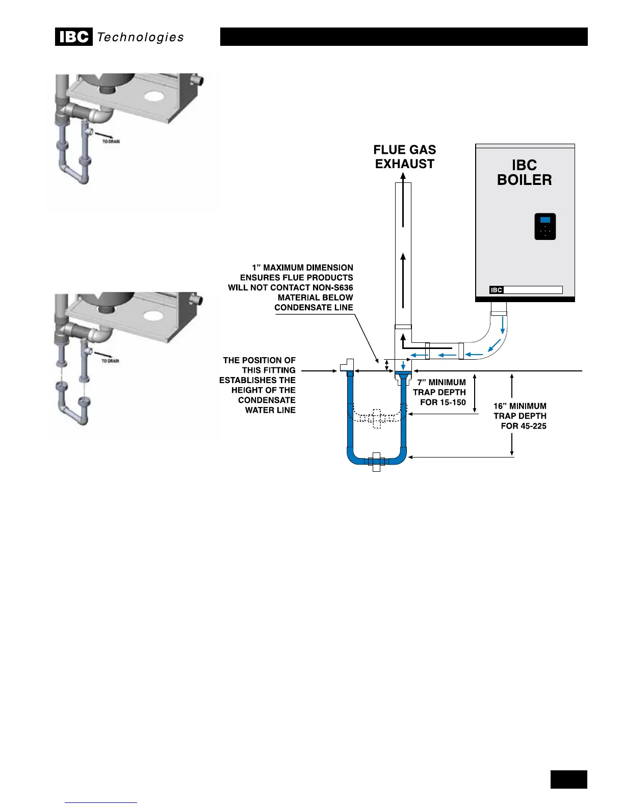
A condensate trap must be installed near the base of the boiler as shown in Figures
14 or 15.ThetrapisformedusingPVCpipe,elbowsandthreadedunionttings.
NOTE: for CPVC vent systems, the connecting tee and bushing should be
formed using CPVC, transitioning to PVC in the wetted section of the trap, where
non-ULC-S636materialsareallowedasthissectionisnotincontactwithue
products. The trap must be installed as follows:
• For the 15-150 model, must be 7” min in height (see Figure 14); with the
conventional vent kit parts supplied with the boiler, approximately 15”
clearance below the boiler is required. For the 45-225 model, the trap shall
have an effective minimum depth of 16” (up to 24” below may be required;
this can be achieved using a conventional drop as shown below or a ball trap
assembly of similar properties).
• Use the supplied vent kit parts to establish the trap in the location shown
below. Do not place the drain connection tee directly at the base of the boiler.
Figure 14: Condensate trap conguration (single union option shown)
Figure 15: Condensate trap
conguration (double union option
shown)
Figure 16: Condensate trap
disassembly for cleaning

 Loading...


