INSTALLATION AND OPERATION INSTRUCTIONS
1-16
VFC 15-150 - VFC 45-225 MODULATING GAS BOILERS
1.5.1.2 WITH PPS VENTING SYSTEMS
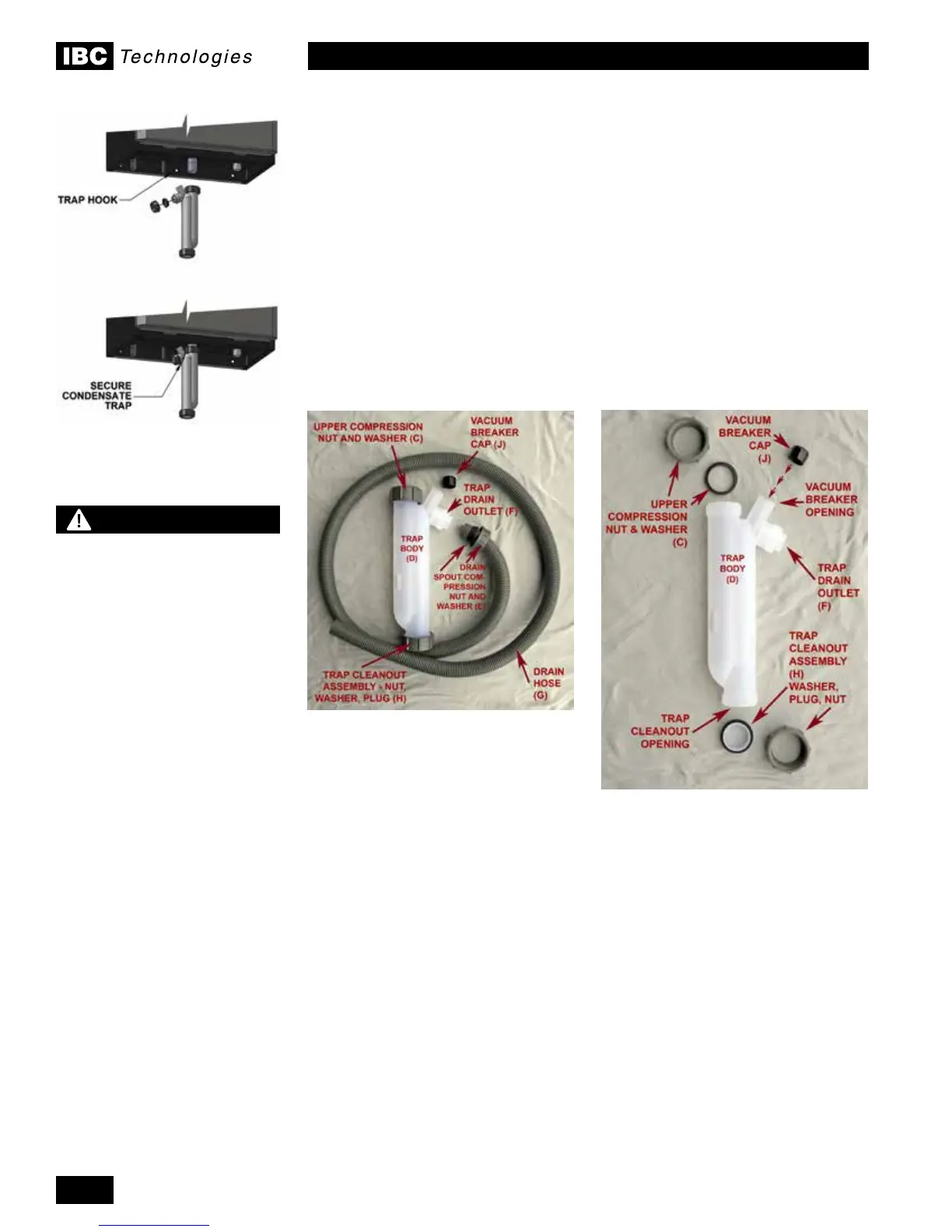
A condensate trap must be installed on the drain connection at the base of the
boiler as shown in Figure 17. Please follow the installation instructions below:
1. Undo Drain Spout Compression Nut (E), remove Drain Hose (G) from Trap
Drain Outlet (F). Place Vacuum breaker cap (J) over the Vacuum breaker
openingandpushrmlyhome.RemoveUpperCompressionNutand
Washer (C) and slide over Boiler Drain Outlet (A). Insert one Trap Hook barb
into the back mounting hole.
2. Fill Trap with water, and slide Trap Body (D) over Boiler Drain Outlet (A).
Swing Trap Hook (B) around the Drain Outlet (F) connection threads. Insert
remaining Trap Hook barb into the front hole. Pull the trap slightly downward
to seat it against the hook and tighten Upper Compression nut (C).
3. Attach Drain Hose (G) and tighten Drain Spout Compression Nut (E).
Figure 17: Condensate trap
installation
WARNING
The Trap Hook must be
installed as instructed and all
trap ttings must be tightened
as instructed to prevent
leakage of ue gasses.
Failure to comply may result
in severe personal injury or
death.
Condensate Trap as shipped
Condensate Trap, disassembled

 Loading...


