1-5
INSTALLATION
VFC 15-150 - VFC 45-225 MODULATING GAS BOILERS
For long vent runs with higher initial exhaust temperature, some jurisdictions
may allow the use of mixed materials for economy: ULC-S636 approved CPVC
for the initial run followed by ULC-S636 approved PVC to the termination (It is
the responsibility of the Installer to conrm that local codes will allow this option).
Ensure appropriate transition glue is used. The installer is responsible to ensure
thatsufcienttemperaturelossisallowedforintheCPVCsectiontofallbelow
the limit for PVC, taking into account the highest possible ambient temperature in
the area of vent travel (e.g. boiler room, attic and/or chase).
EXHAUST VENT MATERIAL – USA
IBC strongly recommends only PPs or CPVC vent component systems approved
under ULC-S636 Standard for Type BH Gas Venting Systems, or stainless steel
Type BH venting systems* are to be used - BUT - many local jurisdictions in the
USA still allow the use of PVC (ULC-S636 or Sch. 40 ASTM D1785 or D2665
andttings)orCPVC(ULC-S636orSch.40/ASTMF441withSch.80ttings);
or CSA approved 3" stainless vent systems. If PVC is to be used, you shall use
a minimum of 10 lineal feet of CPVC, and then transition to PVC using approved
transition glue. The installer shall ensure that vent temperatures in the PVC
section cannot exceed 140°F.
Do not use ABS or any cellular core pipe for exhaust venting.
The boiler offers 2" venting connections. Fittings are to be used to adapt to
the appropriate diameter – see Vent Travel below. Exhaust venting is to be
connecteddirectlytothe2"NPTmalethreadedstainlesssteelttingonthe
bottom of the pressure vessel using:
• For CPVC (and in the USA only, PVC) systems a 2" CPVC (USA: 2” PVC
allowed) threaded adaptor or 90° elbow adaptor. A condensate trap formed
usingthesuppliedttingsshallbeconsideredpartoftheexhaustandinstalled
near the base of the boiler (see Figure 2).
• for PPs, use IBC’s VFC PPs transition kit as appropriate for the chosen PPs
system:
CENTROTHERM INNOFLUE™ M&G DURAVENT POLYPRO™
KIT# P-166A KIT# P-167A
2” Stainless Coupler (190-044) 2” Stainless Coupler (190-044)
PPs Transition (180-037) PPs Transition (180-040)
Retainer Clip (180-050) Retainer Clip (180-051)
Combustion air piping is connected at the base of the boiler using a standard
2" PVC (ABS) coupler or elbow (see Section 1.4.7). For PPs intake piping, use
standard PPs : 2”Sch 40 adaptor parts from the respective PPs manufacturers.
Venting shall be supported in accordance with applicable code.
*Manufacturers of stainless steel Type BH venting systems must submit
their approved transition tting to IBC for evaluation and written approval.
DANGER
Failure to install PPs adaptor
with retainer clip could cause
release of harmful exhaust
gases into the heated space,
potentially leading to injury
or death.
WARNING
Do not mix PPs venting
materials from different
Manufacturers.
These venting materials are
designed to be installed as
part of a complete system.
Failure to comply may result
in severe personal injury or
death.
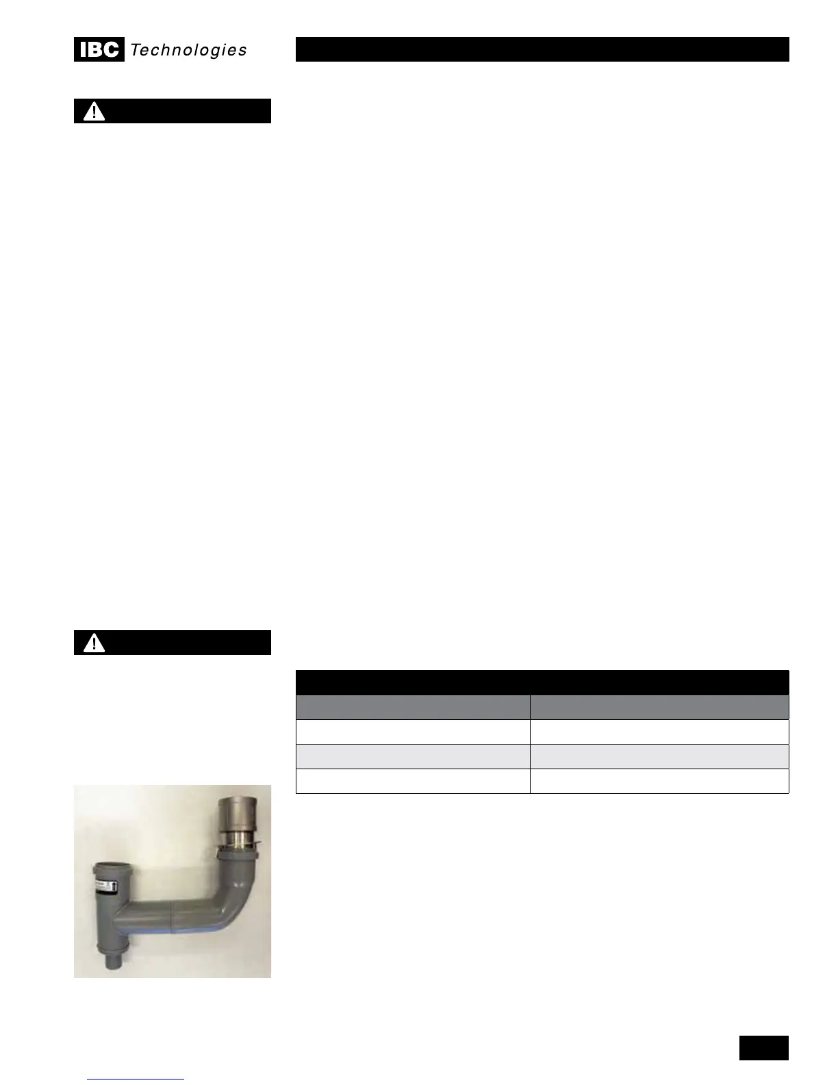
Figure 1c: PP Vent Adaptor
Assembly

 Loading...


