blocks specified by ex. After each data block
of
256 bytes, a
2-byte cyclic redundancy check
(eRe)
is
written. The data bytes
are taken from the memory location pointed at by ES.
The write-byte routine disassembles and writes the byte a bit at a
time
to
the
cassette. The method used
is
to
set Timer 2 to the
period
of
the desired
data
bit. The timer
is
set to a period
of
,.,-.....,
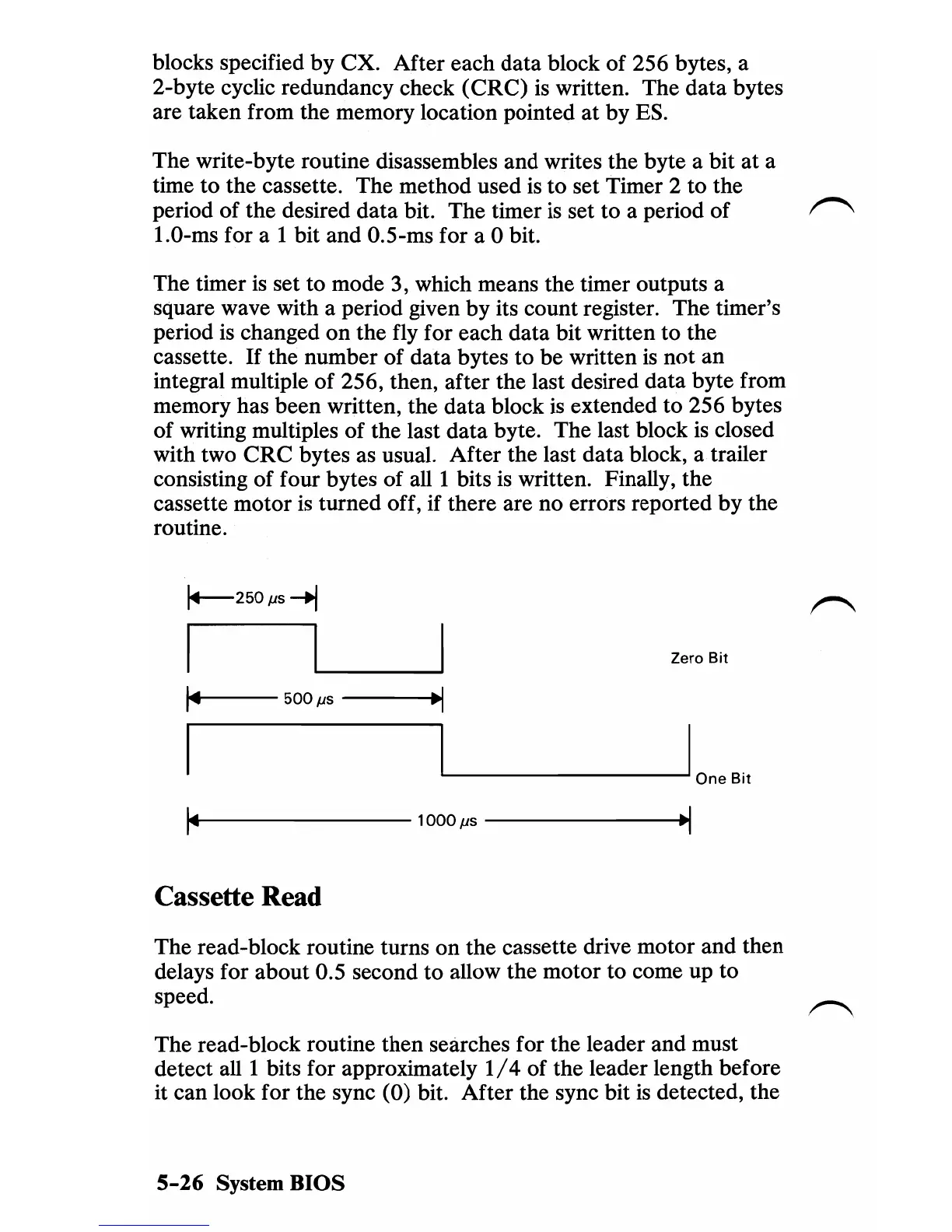
1.0-ms for a I bit and 0.5-ms for a 0 bit.
The timer
is
set to mode 3, which means the timer outputs a
square wave with a period given by its count register. The timer's
period
is
changed
on
the fly for each data bit written to the
cassette.
If
the number
of
data bytes to be written
is
not an
integral multiple
of
256, then, after the last desired data byte from
memory has been written, the data block
is
extended to 256 bytes
of writing multiples of the last data byte. The last block
is
closed
with two
eRe
bytes as usual. After the last data block, a trailer
consisting
of
four bytes
of
alII
bits
is
written. Finally, the
cassette motor
is
turned off, if there are no errors reported by the
routine.
1+--250
fJS
~
Zero
Bit
1~4---
500
fJS
---~.I
'----_----'I .
-
One
Bit
~14---------------1000fJs--------------~·1
Cassette Read
The read-block routine turns on the cassette drive motor and then
delays for about 0.5 second
to
allow the motor to come up to
speed.
The read-block routine then searches for
the
leader and must
detect
alII
bits for approximately
1/4
of
the leader length before
it can look for the sync (0) bit. After the sync bit
is
detected, the
5-26
System BIOS

 Loading...


