The
coprocessor has eight 80-bit registers, which provide the
equivalent capacity of the
40
16-bit registers found in
the
microprocessor. This register space allows constants
and
temporary results
to
be
held in registers during calculations, thus
reducing memory access
and
improving speed as well as bus
availability. The register space can
be
used as a stack
or
as a
fixed register set. When used as a stack, only
the
top two stack
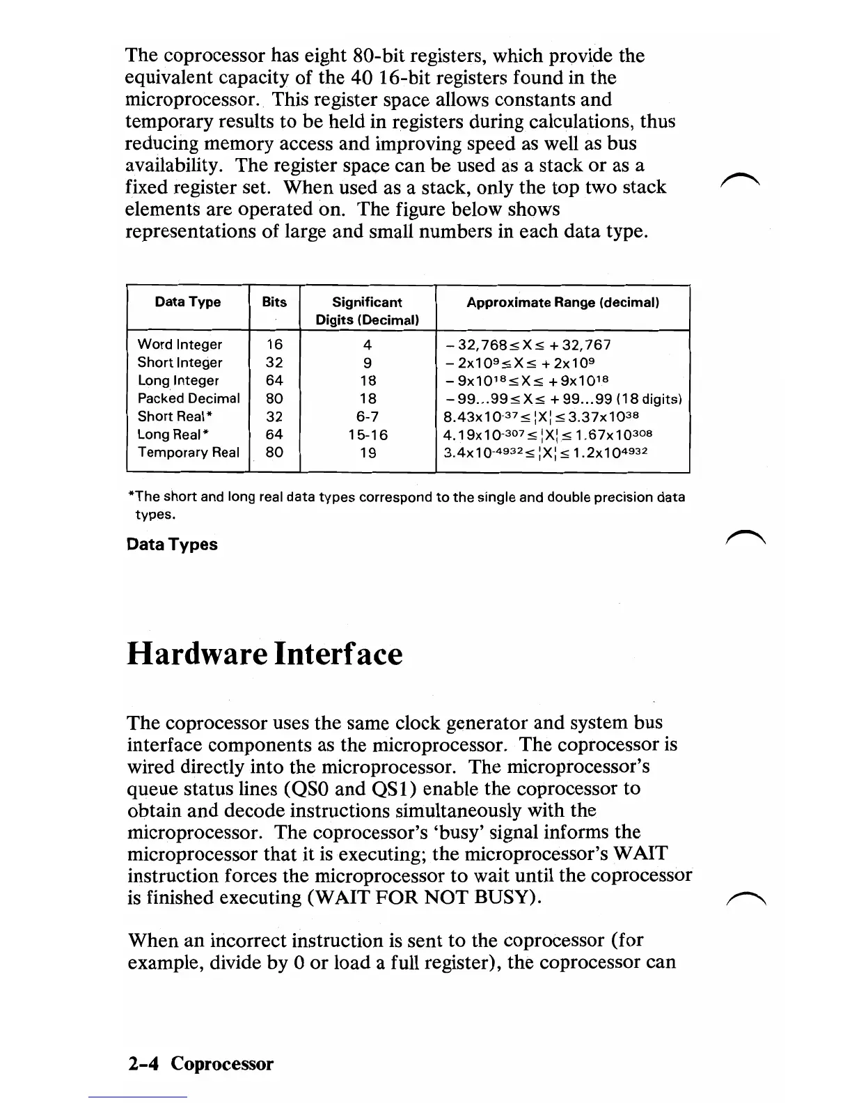
elements are operated on. The figure below shows
representations of large
and
small numbers in each
data
type.
Data Type
Bits
Significant
Approximate
Range (decimal)
Digits
(Decimal)
Word Integer
16
4
-32,768:5X:5
+32,767
Short
Integer
32
9 - 2x1 0
9
:5
X:5 +
2x10
9
Long Integer
64
18
-9x10
18
:5X:5
+9x10
18
Packed Decimal
80
18
-
99
...
99:5
X:5 +
99
...
99
(18
digits)
Short
Real*
32
6·7
8.43x1
0
37
:5
:X::5
3.37x1
0
38
Long Real*
64
15·16
4.19x10-307:5 :X:
:51.67x10
308
Temporary
Real
80
19
3.4x
1 0-
4932
:5
:X::5 1.2x104932
*The
short and long real data
types
correspond
to
the
single and double precision data
types.
Data
Types
Hardware Interface
The coprocessor uses
the
same clock generator
and
system bus
interface components as the microprocessor.
The
coprocessor is
wired directly into the microprocessor.
The
microprocessor's
queue status lines
(QSO
and
QSl)
enable
the
coprocessor to
obtain
and
decode instructions simultaneously with the
microprocessor.
The
coprocessor's 'busy' signal informs the
microprocessor
that
it
is
executing; the microprocessor's WAIT
instruction forces the microprocessor
to
wait until the coprocessor
is finished executing
(WAIT
FOR
NOT
BUSY).
~
When
an
incorrect instruction
is
sent
to
the coprocessor (for
example, divide
by
0
or
load a full register),
the
coprocessor can
2-4
Coprocessor

 Loading...


