The speaker connection is a 4-pin Berg connector. See "System
Board Component Diagram," earlier in this section, for speaker
connection or placement.
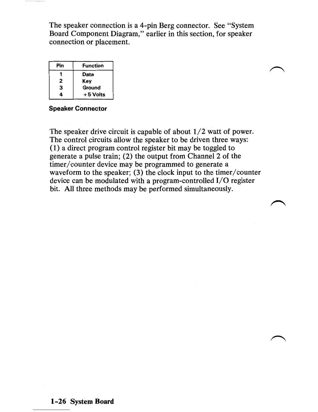
Pin
Function
1 Data
2 Key
3 Ground
4 + 5
Volts
Speaker Connector
The speaker drive circuit
is
capable of about
1/2
watt of power.
The control circuits allow the speaker to be driven three ways:
(1)
a direct program control register bit may be toggled
to
generate a pulse train;
(2)
the output from Channel 2 of the
timer/
counter device may be programmed to generate a
waveform to the speaker;
(3)
the clock input to the timer/counter
device can be modulated with a program-controlled
I/O
register
bit. All three methods may be performed simultaneously.
1-26
System Board

 Loading...


