v The top of the display, as shown in the following figure, shows 01 V=F.
3. Press the power button (A), as shown in the following figure, on the control panel.
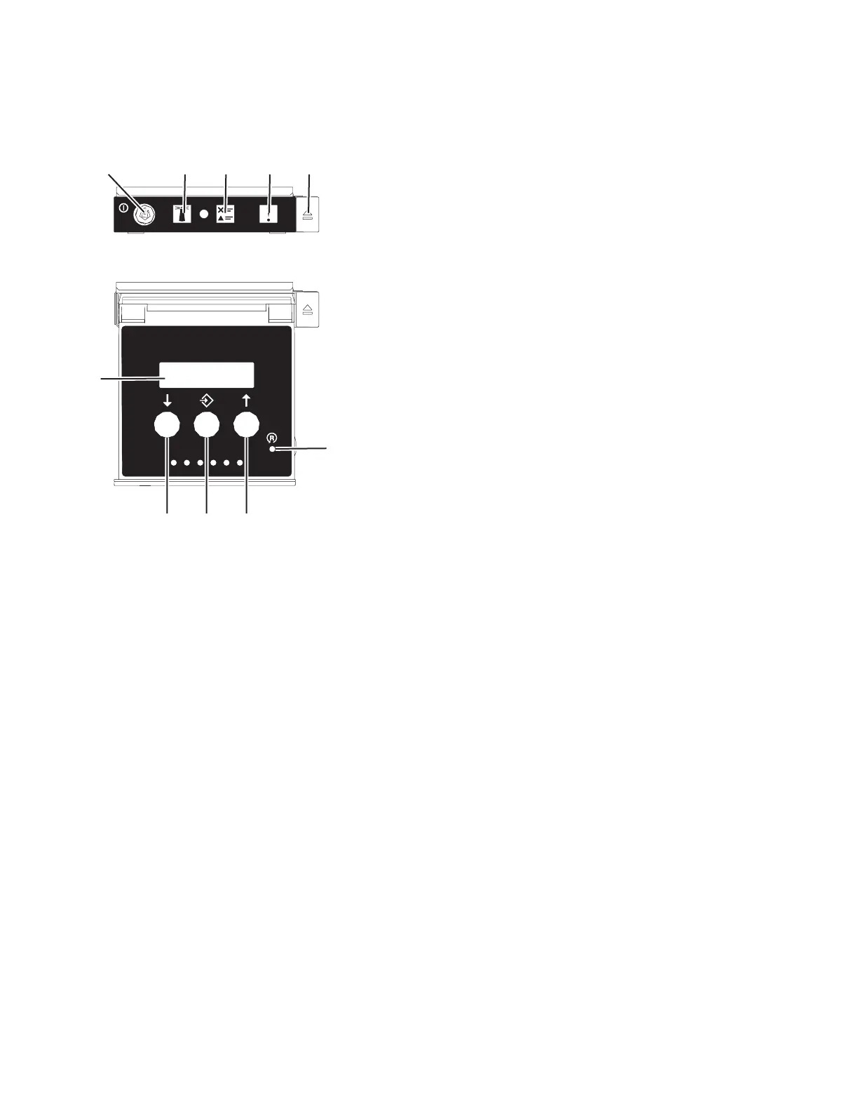
v A: Power-on button
– A constant light indicates full system power to the unit.
– A flashing light indicates standby power to the unit.
– There is approximately a 30-second transition period from the time the power-on button is
pressed to when the power LED goes from flashing to solid. During the transition period, the
LED might flash faster.
v B: Enclosure identify light
– A constant light indicates the identify state, which is used to identify a part.
– No light indicates that the system is operating normally.
v C: System information light
– No light indicates that the system is operating normally.
– Light on indicates that the system requires attention.
v D: Enclosure fault roll-up light
– A constant light indicates a fault in the enclosure.
– No light indicates that the system is operating normally.
v E: Eject button
v F: Function/Data display
v G: Pinhole reset button
v H: Decrement button
v I: Enter button
v J: Increment button
4. Observe the following aspects after pressing the power button:
ABCDE
F
G
HI
J
Front View
Top View
P8HB5500-1
Figure 46. Control panel
50 Power Systems: Installing the 5887 disk drive enclosure