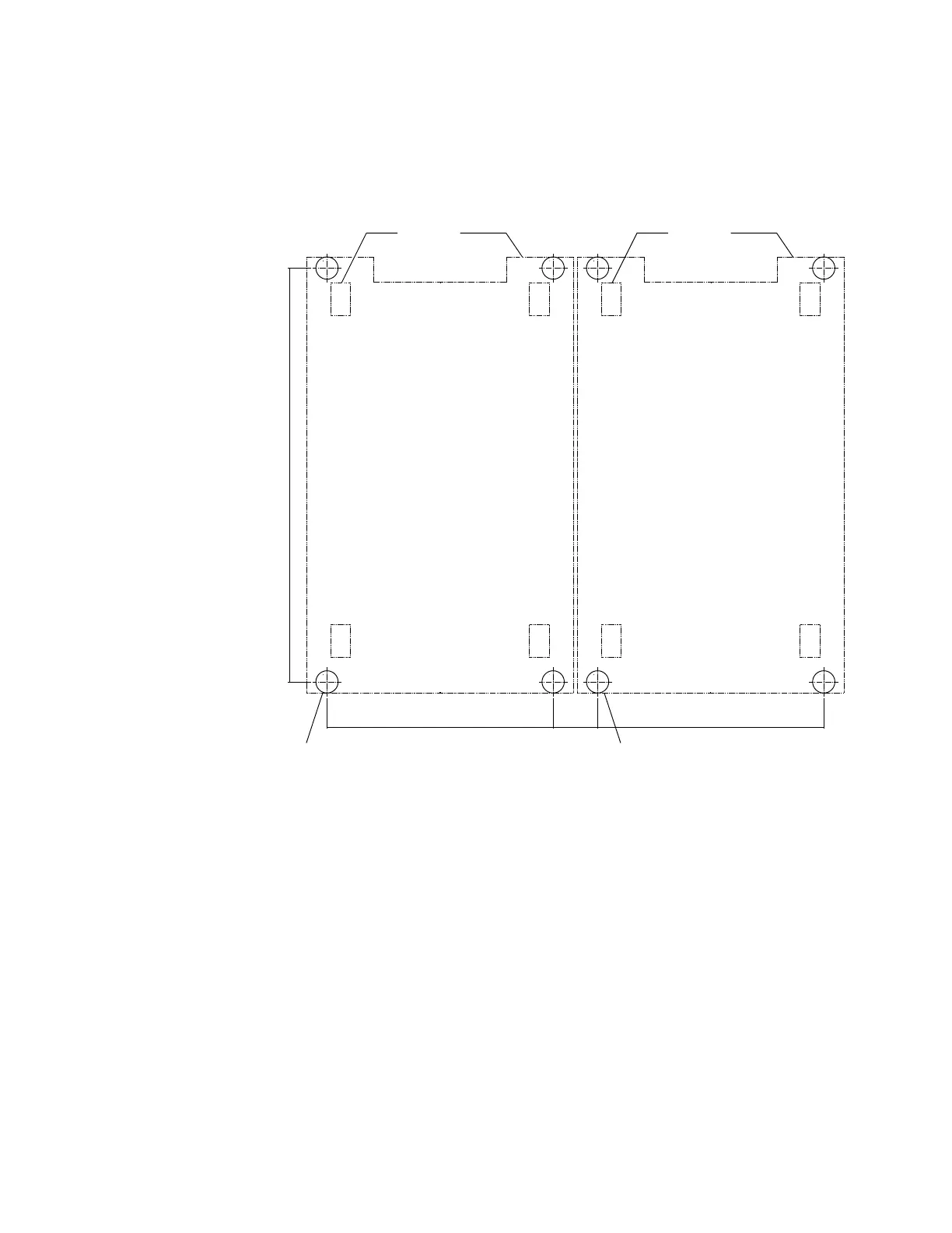
v One cable cutout for power and other cables that connect to the frame.
Use Figure 21 as a guide for the location and dimensions of these openings.
The pattern repeats for each frame in the configuration. Dimensions are in
millimeters (inches).
2. Obtain four fasteners (per frame) that are heavy-duty concrete or slab floor
eyebolts. The four fasteners per frame are different than the eight fasteners per
frame that are needed for non-raised floor installation. These eyebolts are used
to secure the earthquake resistance kit. Work with your consultant or structural
engineer to determine the correct eyebolts to use, but each eyebolt must meet
the following specifications.
v Each eyebolt must withstand a 3600-pound pull force.
v The dimensions of the eyebolt must allow the turnbuckle lower jaw of the kit
to fit over the eyebolt and allow the spacer of earthquake resistance kit to fit
inside the eye. See Figure 22 on page 150 and Figure 23 on page 151.
(2X) 1144
(45.0)
(4X) 52
(2.05)
(2X) 483
(19.01)
121.5
(4.78)
FRONT
REAR
(caster) (frame base)
(4X) 52
(2.05)
(2X) 483
(19.01)
FRONT
REAR
(caster) (frame base)
f2c02319
Figure 21. Locations for the cable cutouts, rubber bushing holes on raised floors, and eyebolt
on concrete floors
Chapter 6. Delivery and installation requirements 149
 Loading...