EasyManuals Logo

IBM Power System 9009-41A User Manual

IBM Power System 9009-41A
170 pages
To Next Page IconTo Next Page
To Previous Page IconTo Previous Page
Page #135 background imageLoading...
Page #135 background image
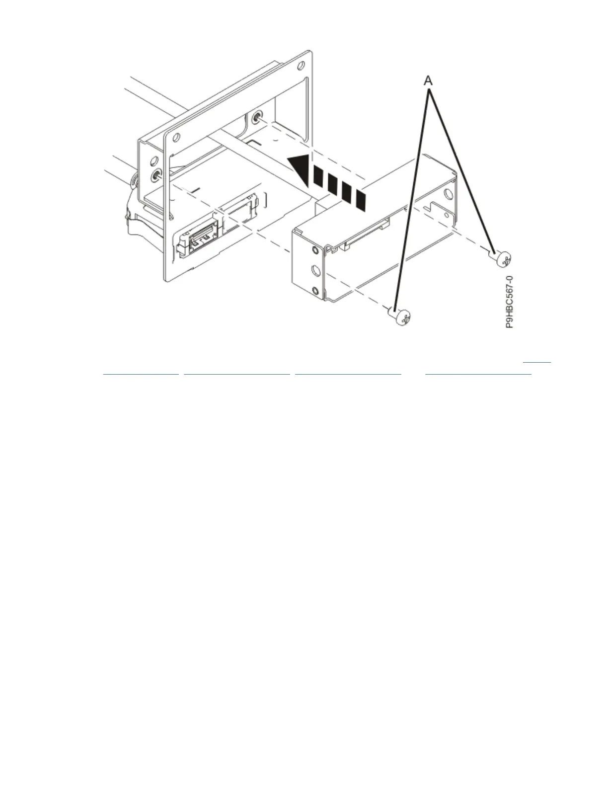
Figure 116. Installing the control panel display cable into the housing for a rack-mounted system
3. For a rack-mounted system, insert the control panel display cable into the system as shown in Figure
117 on page 122, Figure 118 on page 123, Figure 119 on page 124, and Figure 120 on page 125.
Pass the cable through the channel along the side of the chassis, being careful not to catch the cable
on any components as you insert it.
Control panel cables for the 9009-41A, 9009-42A, or 9223-42H
121

Questions and Answers:

Question and Answer IconNeed help?

Do you have a question about the IBM Power System 9009-41A and is the answer not in the manual?

IBM Power System 9009-41A Specifications

General IconGeneral
ProcessorPOWER9
Memory slots16
Form factor4U
Operating systems supportedAIX, IBM i, Linux
Processor cores4
Processor threads32
Processor speed2.8 GHz
Maximum memory1024 GB
StorageSAS SFF Gen3 HDD/SSD, NVMe SSD