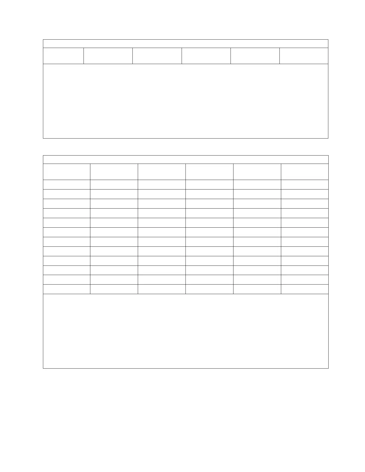
Floor Loading for Systems with Slimline Covers
Condition
5
a (sides)
mm (in.)
b (front)
mm (in.)
c (back
mm (in.)
Without IBF
kg/m
2
(lb./ft.
2
)
With IBF
kg/m
2
(lb./ft.
2
)
Notes:
1. Service clearance is independent from weight distribution distance and must be at least 47 in. for the front of the
frame and 36 in. for the rear of the frame (measured from the base frame).
2. Weight-distribution areas should not be overlapped.
3. Floor-loading weight distribution distances should not exceed 762 mm (30 in.) in any direction when measured
from the base frame.
4. Consult a professional, such as a structural engineer, if you are unsure of the floor-load rating of your facility.
5. The “Condition” is the description within the table that indicates the side, front, and rear weight shedding
distances.
The following table shows floor-loading specifications for systems with acoustical covers.
Floor Loading for Systems with Acoustical Covers
Condition
5
a (sides)
mm (in.)
b (front)
mm (in.)
c (back
mm (in.)
Without IBF
kg/m
2
(lb./ft.
2
)
With IBF
kg/m.
2
(lb./ft
2
)
1 25 (1.0) 254 (10.0) 254 (10.0) 1121.9 (229.8) 1221.3 (250.1)
2 25 (1.0) 508 (20.0) 508 (20.0) 900.2 (184.4) 977.6 (200.2)
3 25 (1.0) 762 (30.0) 762 (30.0) 759.0 (155.4) 822.3 (168.4)
4 254 (10.0) 254 (10.0) 254 (10.0) 758.3 (155.3) 821.6 (168.3)
5 254 (10.0) 508 (20.0) 508 (20.0) 617.2 (126.4) 666.5 (136.5)
6 254 (10.0) 762 (30.0) 762 (30.0) 527.4 (108.0) 567.7 (116.3)
7 508 (20.0) 254 (10.0) 254 (10.0) 575.2 (117.8) 620.3 (127.0)
8 508 (20.0) 508 (20.0) 508 (20.0) 474.7 (97.2) 509.8 (104.4)
9 508 (20.0) 762 (30.0) 762 (30.0) 410.7 (84.1) 439.4 (90.0)
10 762 (30.0) 254 (10.0) 254 (10.0) 473.9 (97.1) 509.0 (104.2)
11 762 (30.0) 508 (20.0) 508 (20.0) 395.9 (81.1) 423.2 (86.7)
12 762 (30.0) 762 (30.0) 762 (30.0) 346.2 (70.9) 368.5 (75.5)
Notes:
1. Service clearance is independent from weight-distribution distance and must be at least 45 in. at the front of the
frame and 36 in. at the rear of the frame (measured from the base frame).
2. Weight-distribution areas should not be overlapped.
3. Floor-loading weight distribution distances should not exceed 762 mm (30 in.) in any direction when measured
from the base frame.
4. Consult a professional, such as a structural engineer, if you are unsure of the floor-load rating of your facility.
5. The “Condition” is the description within the table that indicates the side, front, and rear weight shedding
distances.
Floor loading for the system is illustrated in the Proposed Floor Layout for Multiple Systems in
“Considerations for Multiple System Installations” on page 115.
Chapter 2. Physical Characteristics of Systems 99

 Loading...

