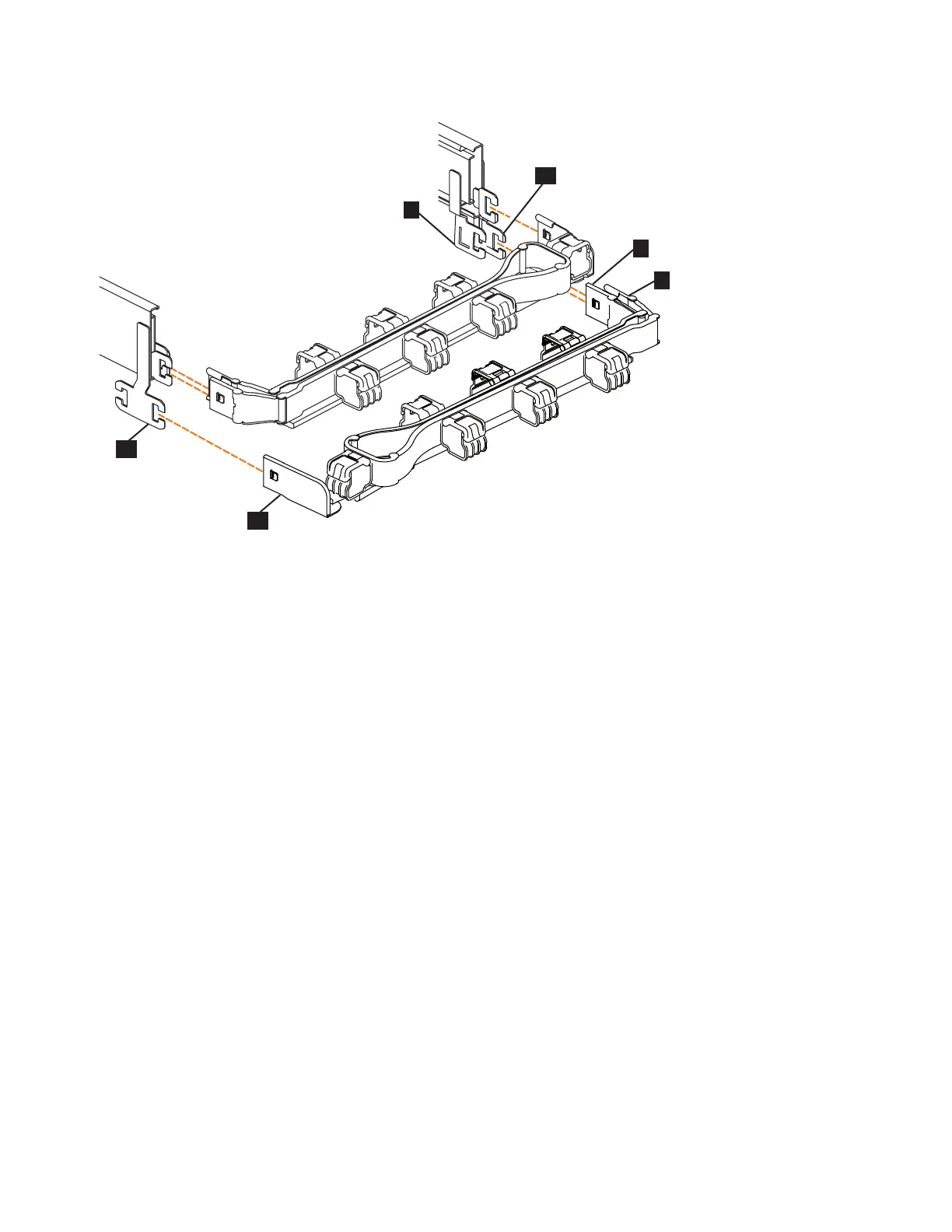
6. Remove the connector base on the lower CMA assembly (▌11▐) from the
connector on the left support rail (▌12▐), as Figure 44.
7. Remove the inner connector of the lower CMA assembly (▌9▐) from the outer
member of the right support rail (▌10▐), as shown in Figure 44.
8. Remove the outer connector of the lower CMA assembly (▌7▐) from the inner
member of the right support rail (▌8▐), as shown in Figure 44.
Replace the CMA assembly
9. To reinstall the CMA, or replace it with one from FRU stock, follow the
procedure in “Installing or replacing the cable-management arm: 2077-92F” on
page 66.
Moving the cable management arms
About this task
To complete most service tasks, you can swing the CMA assemblies out of the way.
You can move each arm independently or you can move both arms. For example,
Figure 45 on page 65 shows that both of the CMA assemblies are swung away
from the rear of the enclosure.
Figure 44. Components of the lower CMA assembly
64 Storwize V5000 Gen2: Quick Installation Guide
 Loading...


