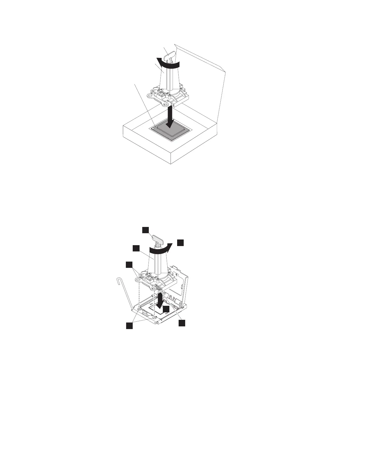
Handle
Installation
tool
Microprocessor
9. Carefully align the microprocessor installation tool over the microprocessor
socket. Twist the handle of the microprocessor tool counterclockwise to insert
the microprocessor into the socket.
Attention: The microprocessor fits only one way on the socket. You must
place a microprocessor straight down on the socket to avoid damaging the
pins on the socket. The pins on the socket are fragile. Any damage to the pins
may require replacing the system board.
7
5
6
3
4
1
2
10. Close the microprocessor bracket frame.
11. Carefully close the microprocessor release lever to the closed position to secure
the microprocessor in the socket.
12. Install a heat sink on the microprocessor.
Attention: Do not touch the thermal grease on the bottom of the heat sink or
set down the heat sink after you remove the plastic cover. Touching the
thermal grease will contaminate it.
Figure 42 on page 146 shows the bottom surface of the heat sink.
Chapter 4. File module 145
 Loading...


