System-board switches and jumpers
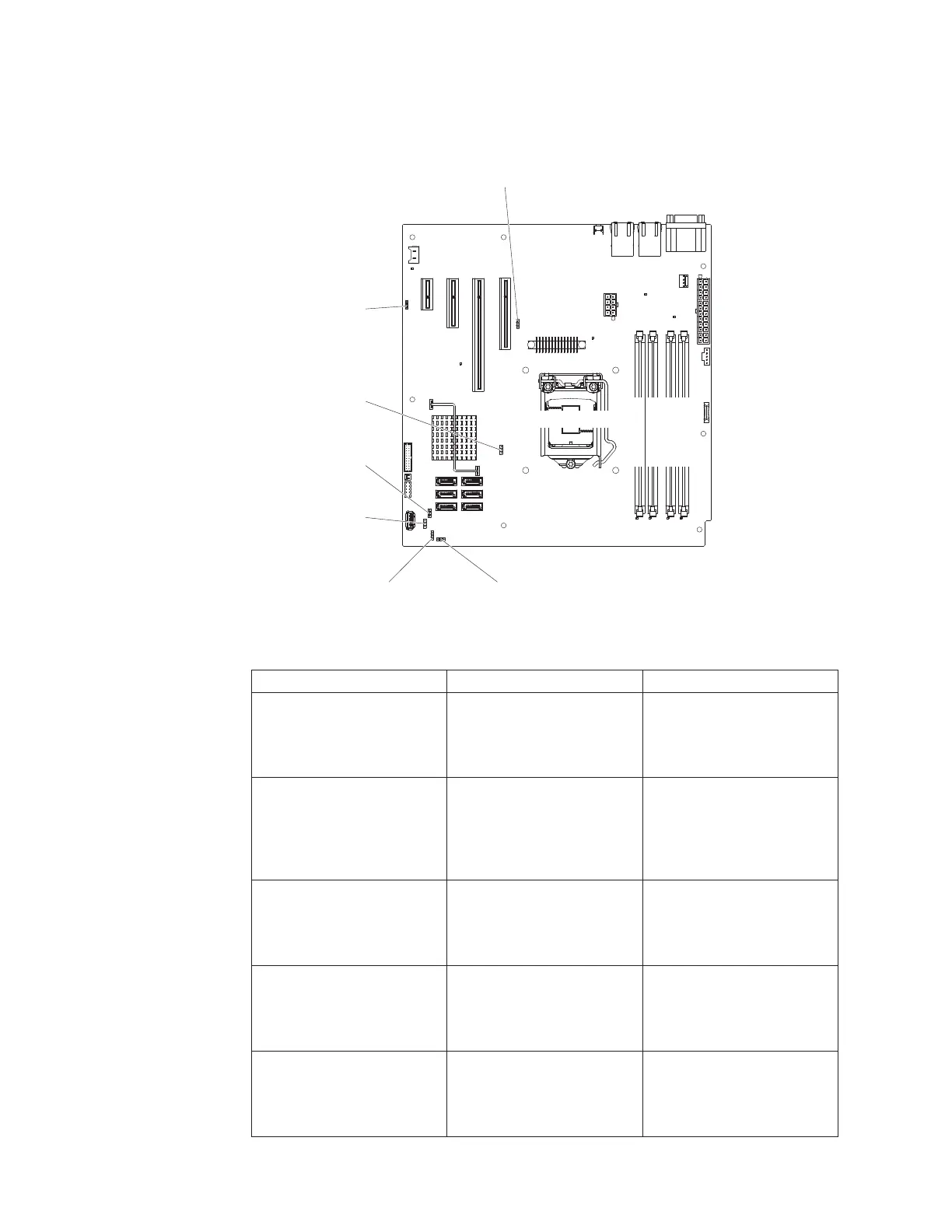
The following illustration shows the jumpers on the system board.
Microprocessor
DIMM 1 Slot
DIMM 2 Slot
DIMM 3 Slot
DIMM 4 Slot
Clean CMOS
jumper (Jp1)
BIOS boot backup
jumper (Jp2)
ME recovery
jumper (Jp8)
ME flash
override
jumper(Jp9)
TPM physical
presence jumper
(Jp10)
TPM initialization
jumper (Jp11)
Low security_N
jumper (Jp22)
IMM SPI half
ROM enable (Jp12)
Table 2. System board jumpers
Jumper number Jumper name Jumper setting
JP1 Clear CMOS jumper
v Pins 1 and 2: Keep CMOS
data (default).
v Pins 2 and 3: Clear CMOS
data.
JP2 BIOS boot backup (boot
block jumper)
v Pins 1 and 2: Boot from
primary BIOS page
(default).
v Pins 2 and 3: Boot from
backup BIOS page.
JP8 ME recovery jumper
v Pins 1 and 2: Normal
(default).
v Pins 2 and 3: Activate ME
recovery.
JP9 ME flash override jumper
v Pins 1 and 2: Normal
(default).
v Pins 2 and 3: Override ME
flash.
JP10 TPM physical presence
jumper
v Pins 1 and 2: Normal
(default).
v Pins 2 and 3: Pull down
TPM.
20 System x3100 M4 Type 2582: Installation and User's Guide

 Loading...


