s. 22 / 40
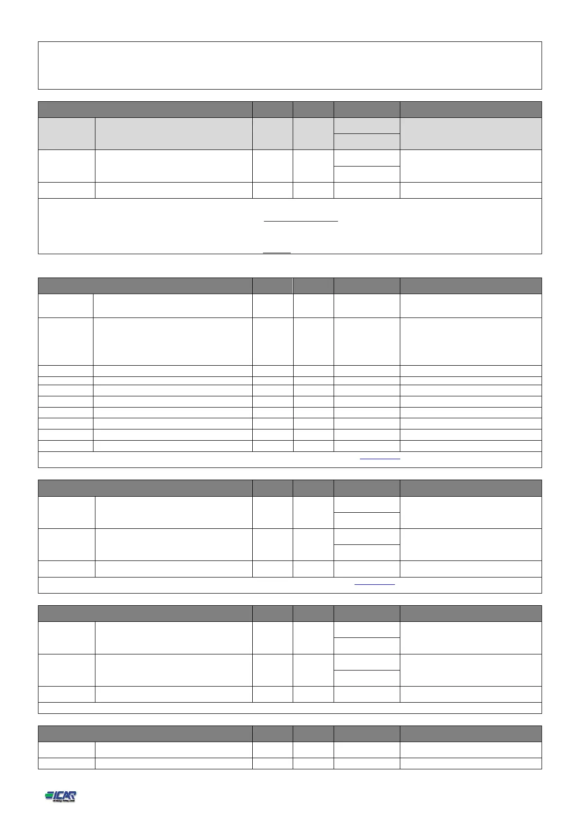
Note: This menu is divided into 32 sections that refer to 32 possible logical steps STP1…STP32 which can be managed by the 8BGA.
P03.n.01 - Weight of step n, referred to the value of the smallest step. A number that indicates the multiple of the power of the current step with reference to the smallest set by
P02.07. If set to OFF the step is disabled and will not be used.
P03.n.02 - Type device delegated the insertion step.
Contactor = Switching with electromechanical contactor. On this step the time of reconnection is used.
Static = Electronic thyristor switching. On this step the time of reconnection is not considered . Used for Fast power factor correction.
Note: This menu is divided into 16 sections that refer to 16 possible digital outputs OUT1…OUT16, which can be managed by the master 8BGA; OUT81..OUT08 on the base
board and OUT09…OUT16 on any installed expansion modules.
P04.n.1 – Selects the functions of the selected output (see programmable chapter 25. Outputs functions table).
P04.n.2 – Index associated with the function programmed in the previous parameter. Example: if the output function is set to Step x, and you want this output to be energized when
there is the step 10 insertion, then P04.n.02 should be set to value 10 or If the output function is set to Alarm xx, and you want this output to be energized for alarm A31,
then P04.n.02 should be set to value 31.
P04.n.3 - Sets the state of the output when the function associated with the same is inactive: NOR = output de-energized, REV = output energized.
Slave01
Slave02
Slave03
…
Slave08
For more information download the complete manual of the RPC 8BGA power factor controller from the web site www.icar.com download area concerning the low voltage power
factor correction systems.
For more information download the complete manual of the RPC 8BGA power factor controller from the web site www.icar.com download area concerning the low voltage power
factor correction systems.
See above, referred to slave 08
(see Input functions table)
 Loading...