Due to Ice Air’s ongoing product development programs, the information in this document is subject to change without notice.
6
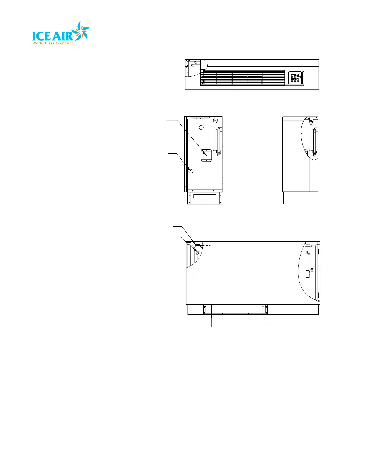
AIR INLET AREA
FILTER LOCATED INSIDE
AND AT TOP OF
OUTLET PIPE
INLET PIPE
TOP VIEW
RIGHT SIDE VIEW
JUNCTION
BOX
HOLE FOR
DRAIN HOSE
FRONT VIEW
Before You Begin
1. Locate the unit where it can evenly
distribute air throughout the room
without obstructions. Units should be
installed no closer than 12” apart when
two units are side by side. A vertical
clearance of 60” should be maintained
between units.
2. Ensure the wall is structurally sound to
support the weight of the unit.
3. Adequate and continuous water flow
must be maintained for proper and
safe unit operation. Ensure adequate
drainage is also available.
4. Follow all applicable codes for
installation.
5. Dedicated electrical circuitry and power
supply is required to properly energize
the Ice Air unit. Verify the amperage of
the dedicated electrical service to the
unit is correct and the unit can reach the
power supply.
6. Position the unit so the air filter can
be removed easily and required
maintenance can be performed without
interference.
7. A minimum obstructed distance of 36”
should be kept around the unit.
IMPORTANT: To avoid permanent damage
to the unit, DO NOT operate during
construction in an open space or as a
supplemental heating and cooling source
during construction.
 Loading...