Due to Ice Air’s ongoing product development programs, the information in this document is subject to change without notice.
7
Installation
Storage
• Ensure all equipment is stored in a clean
and dry area.
• Ensure all equipment is properly covered
and protected while at job site. Keep
coverings on units until installation is
complete. Precautions must be taken
in areas where construction is still
underway to prevent any damage to the
equipment.
Chassis Pre-Installation
• Ensure refrigerant circuit is free of all
damages and kinks.
• Check that all electrical connections are
clean and secure.
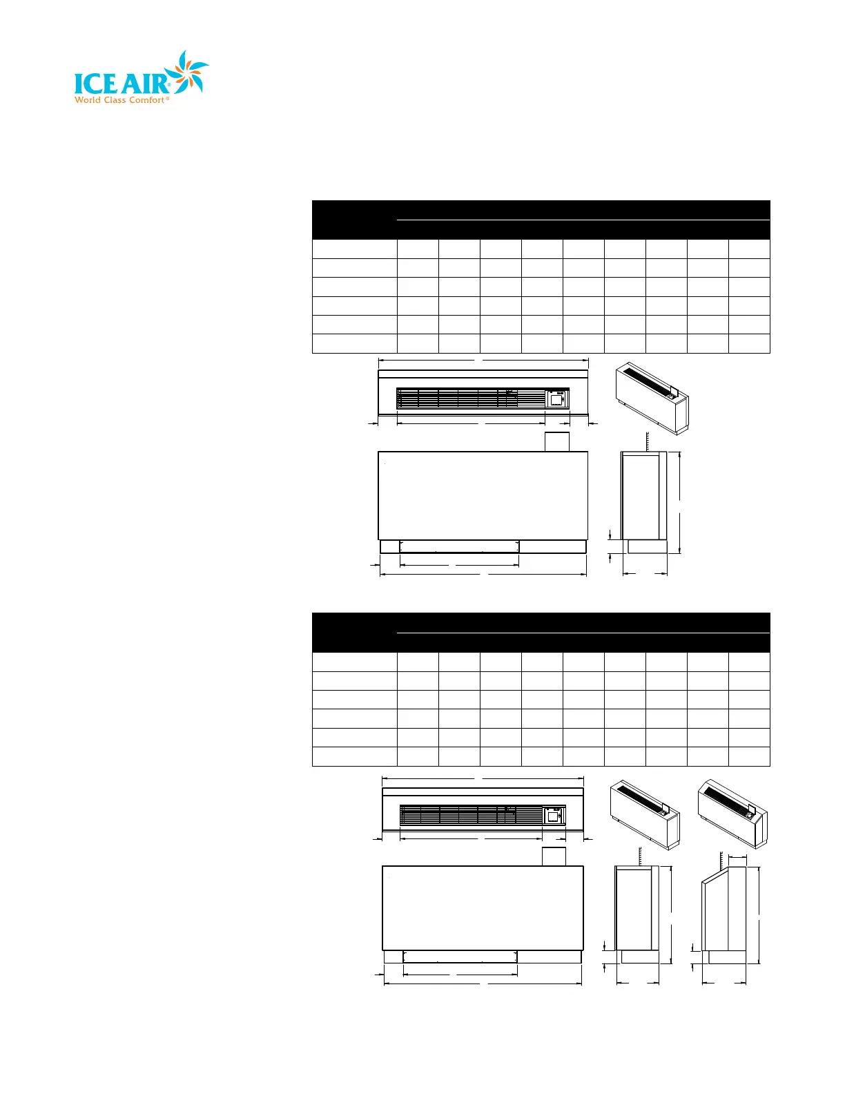
Dimensional Drawing
D
I
B
A
C
TOP VIEW
F
G
H
RIGHT VIEW
EE
FLAT TOP
ISOMETRIC
VIEW
G
SLOPE TOP
H
4.875
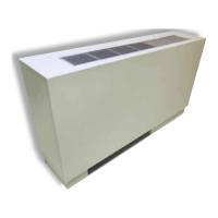
D
I
B
A
C
TOP VIEW
F
G
H
RIGHT VIEW
F
RIGHT VIEW
EE
FLAT TOP
ISOMETRIC
VIEW
FLAT TOP
SLOPE TOP
Model No.
Dimensions (inches)
A B C D E F G H I
5CHPW09 46 22 29.5 45 5 11 3.5 25.25 5.125
5CHPW13 46 22 29.5 45 5 11 3.5 25.25 5.125
8CHPW09 46 22 29.5 45 5 11 3.5 25.25 5.125
8CHPW13 54 30 37.5 53 5 11 3.5 25.25 5.125
8CHPW16 54 30 37.5 53 5 11 3.5 25.25 5.125
8CHPW19 54 30 37.5 53 5 11 3.5 25.25 5.125
Model No.
Dimensions (inches)
A B C D E F G H I
5CHPW09-ZS 46 22 29.5 45 5 11 3.5 24.5 5.125
5CHPW13-ZS 46 22 29.5 45 5 11 3.5 24.5 5.125
8CHPW09-ZS 46 22 29.5 45 5 11 3.5 24.5 5.125
8CHPW13-ZS 54 30 37.5 53 5 11 3.5 24.5 5.125
8CHPW16-ZS 54 30 37.5 53 5 11 3.5 24.5 5.125
8CHPW19-ZS 54 31 38 53 5 11 3.5 24.5 5.125