Due to Ice Air’s ongoing product development programs, the information in this document is subject to change without notice.
8
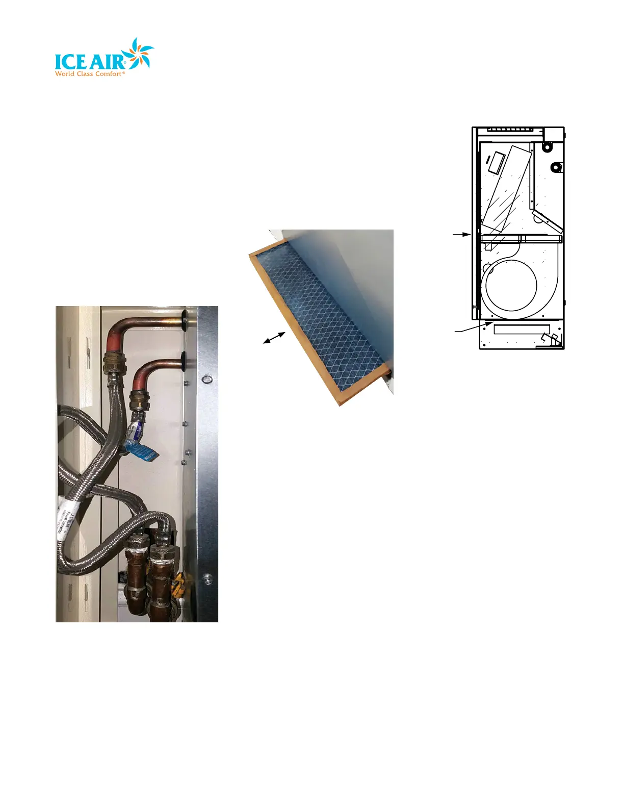
Piping Installation
Ice Air’s Console Water Source Heat Pump
comes with standard Supply and Return
Water pipes on both left and right side of the
unit. Either can be connected for immediate
use, however, the remaining pipes must be
closed off using the enclosed plug. Connect
the pipes using a Braided Steel Hose as
shown below. The condensate tube will be
on the right-hand side and arrive with a hose
clamp to attach to the building’s condensate
pipes.
Units are typically shipped with plugs on
piping connections, and field installer
removes the plugs on the field piping side.
Water piping terminates in the same location
regardless of the connection and valve
options.
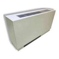
Filter Installation
Each unit is delivered with a filter for the filter
rack, which can be found at the bottom of
the unit as shown below. In order to install
the filter, slide the piece horizontally into the
slot. Ensure the filter is effectively pushed to
the end.
FILTER SLOT
ENCLOSURE
FRONT COVER
Filter slides
horizontally in
grooves at bottom
of unit.