3 - 1
SECTION 3 CIRCUIT DESCRIPTION
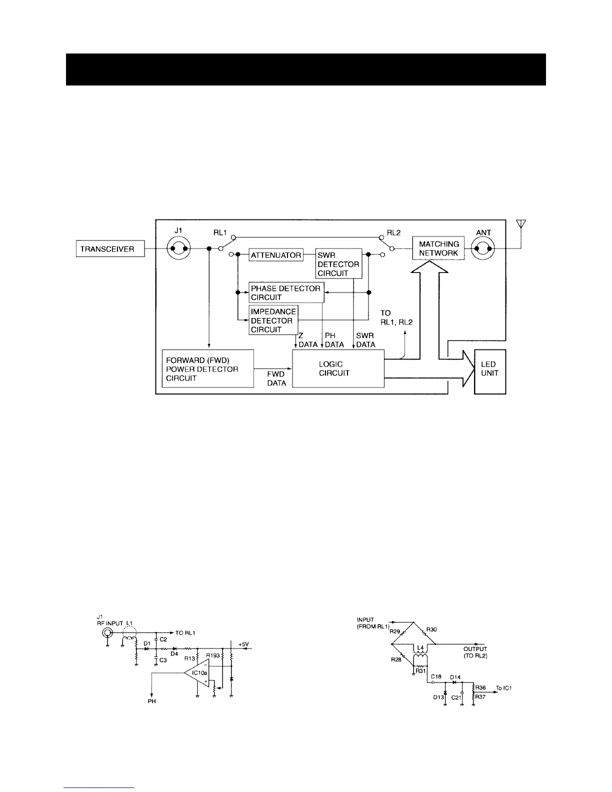
3-1 GENERAL
An 8-bit microprocessor controls the AT-130/AT-130E/AT-
140. The tuner matches the antenna system to the trans-
ceiver by using four kinds of detector circuits. These circuits
are:
(1) FORWARD POWER DETECTOR
(2) SWR DETECTOR
(3) PHASE DETECTOR
(4) IMPEDANCE DETECTOR
Detailed descriptions of each circuit as follows.
• GENERAL
3-2 FORWARD (FWD) POWER DETECTOR
CIRCUIT
This circuit ensures the input power from the transceiver is
low enough to be handled by the attenuator within the tuner.
In the TUNER UNIT, L1 and D1 detects the RF input current.
C2 and C3 divide the detected voltage and feed it to IC10a.
3-3 SWR DETECTOR CIRCUIT
The reflected power from the antenna system provides a
detection voltage.
The voltage doubler, consisting of D13 and D14, rectifies
this voltage and passes through the voltage divider formed
by R36 and R37.
These SWR data from voltage divider feed into IC1, The
CPU. The CPU controls the setting of the coils and capaci-
tors in the matching network.
• FORWARD POWER DETECTOR CIRCUIT • SWR DETECTOR CIRCUIT

 Loading...


