3 - 2
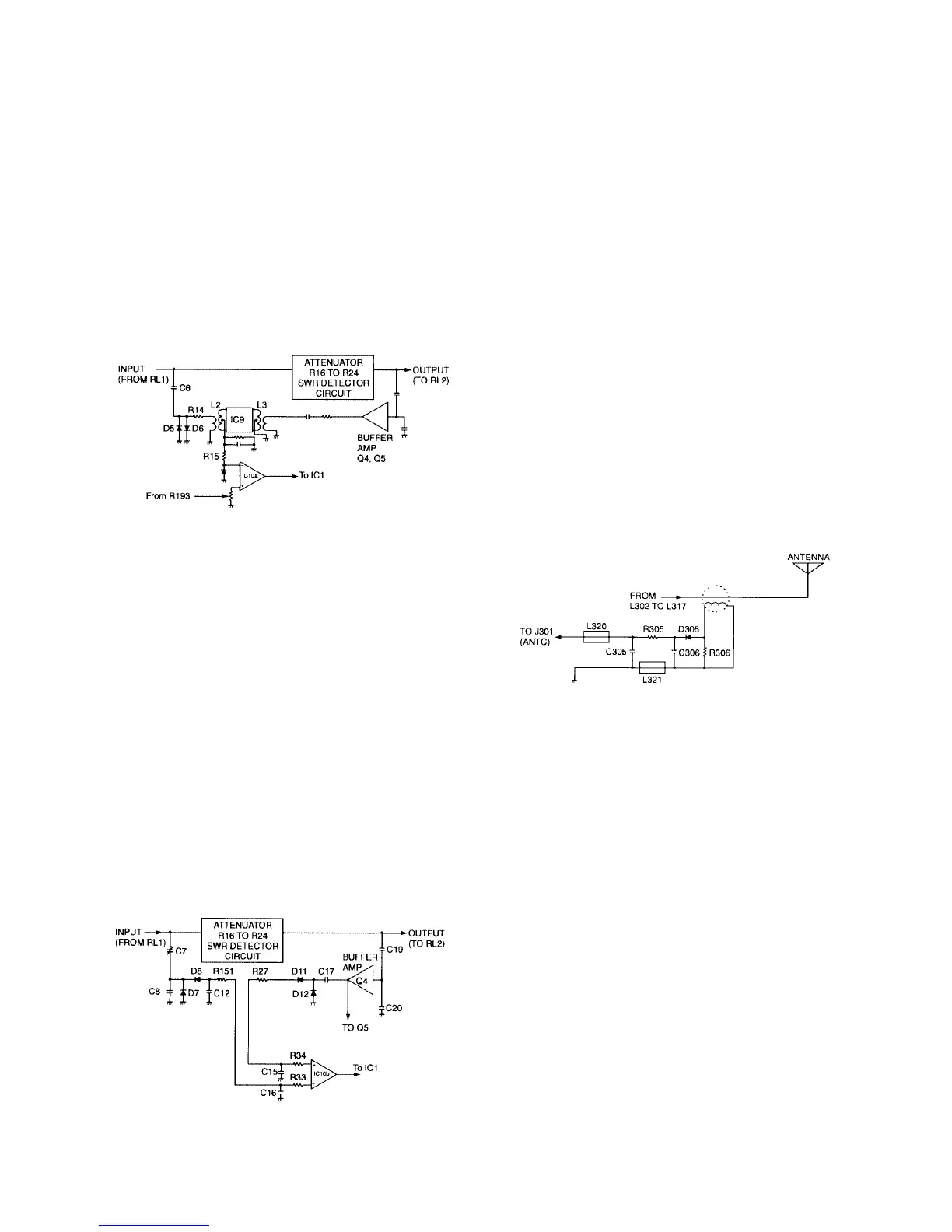
3-4 PHASE DETECTOR CIRCUIT
This circuit consists of L2, L3 and IC9. The phase detector’s
purpose is to detect reactance components and provide a
pure resistance.
The output of IC9 is a reference voltage of approximately
4 V when the load of L3 is a pure resistance with no reac-
tance. An inductive load produces an output voltage from
IC9 which is lower than the reference voltage, whereas, a
capacitive load produces an output voltage higher than the
reference voltage. IC10a amplifies the output voltage and
passes it to comparator IC10a.
3-5 IMPEDANCE DETECTOR CIRCUIT
The tuner uses an attenuator to reduce the transmit power
to a very low level. The low power minimizes the risk of inter-
ference to other stations while matching an antenna to the
transmitter.
The VSWR at the input terminal is usually close to 1:1 even
with a large change of impedance at the attenuator output
due to the 16 dB of isolation between the input and the
matching network.
The circuit uses the constant voltage at D7 and D8 on The
TUNER unit as a reference. If the impedance of the attenu-
ator output is higher than 50 Ω, the detected voltage by D11
and D12 is HIGH. If the impedance is lower than 50 Ω, the
voltage is LOW. Both the reference and detected voltages
feed to comparator IC10b.
3-6 LOGIC CIRCUIT
IC1, The CPU, controls the antenna matching network. The
CPU receives +5V through IC8 when DC power is applied to
the tuner. This voltage initializes the CPU. The stored pro-
gram in the Read Only Memory (ROM) IC12 sets each relay
to the initial condition.
The tuning program begins only if the START line is at LOW
level. RL1 and RL2 activate when RF power at the input
antenna connector from the transceiver is present at an
appropriate level (See Section 6-2).
The data from the previously described detectors (input RF
power, reflected RF power, phase difference, impedance dif-
ference) feed into the CPU. The coil data then passes to
IC4, the capacitor data to IC3 and the control data to IC2
according to the tuning program.
3-8 ANTENNA CURRENT DETECTOR CIRCUIT
(MANUAL UNIT — Europe version only)
On the MANUAL UNIT, L319 detects the antenna current.
D305 rectifies the detected voltage and feed it to J301
through low-pass filter comprising R305, C305 and C306.
• PHASE DETECTOR CIRCUIT
• IMPEDANCE DETECTOR CIRCUIT
• ANTENNA CURRENT DETECTOR CIRCUIT