2.
TX/RX
Switching
Circuit
When the
PTT
SWITCH
on the
microphone
is pushed,
pin 5
of J1
becomes
LOW and
thecolfectorof
Q4
becomes
HIGH.
Q3
reverses
this signal to supply
the
transmit mode
signal
to
the SEND port on
the CPU.
3.
TX Control
Pin 13on IC3A is
connected to
the MUTE port on the CPU to
eliminate unwanted
signals
from
being
transmitted. If an
out-of-barid
frequency is selected,
the output
level
from
ICS A Stays
LOW
to
mute the transmit signal when the
PTT
SWITCH on the
microphone
is
pressed.
4.
Power
ON
Reset Circuit
When the
transceiver
is turned
ON, a signal from IC4C is
Supplied to IC3C and
the
main
matrix
on
the LOGIC A UNIT.
If the FUNCTION SWITCH is pressed
when the
transceiver
is being
switched
ON, IC3 sends a reset
signal
to
the
CPU.
5. Scan Stop
Circuit
When
the SQL Ssignal from the
MAIN
UNIT
is
HIGH,
it turns
ONOBand passes
thesignal to the
SCAN STOP
port
on the
CPU. Also, 06
controls
the
D13 receive LED.
a.
Mic UP/DOWN Circuit
When
the
UP/DOWN SWITCH on the
microphone
is
pressed,
asignal
is
supplied to
the MIC CK port
on the GPU.
When the UP
SWITCH
is
pushed, the collector
of
ICS
becomes
HIGH. When
the DOWN
SWITCH is pushed, the
collectorof
IC5 becomes LOW. The
CPU
receives
this signal
from the U/D
port
on
the CPU to control
the
microphone
scanning
function
3-4-3
LOGIC B UNIT
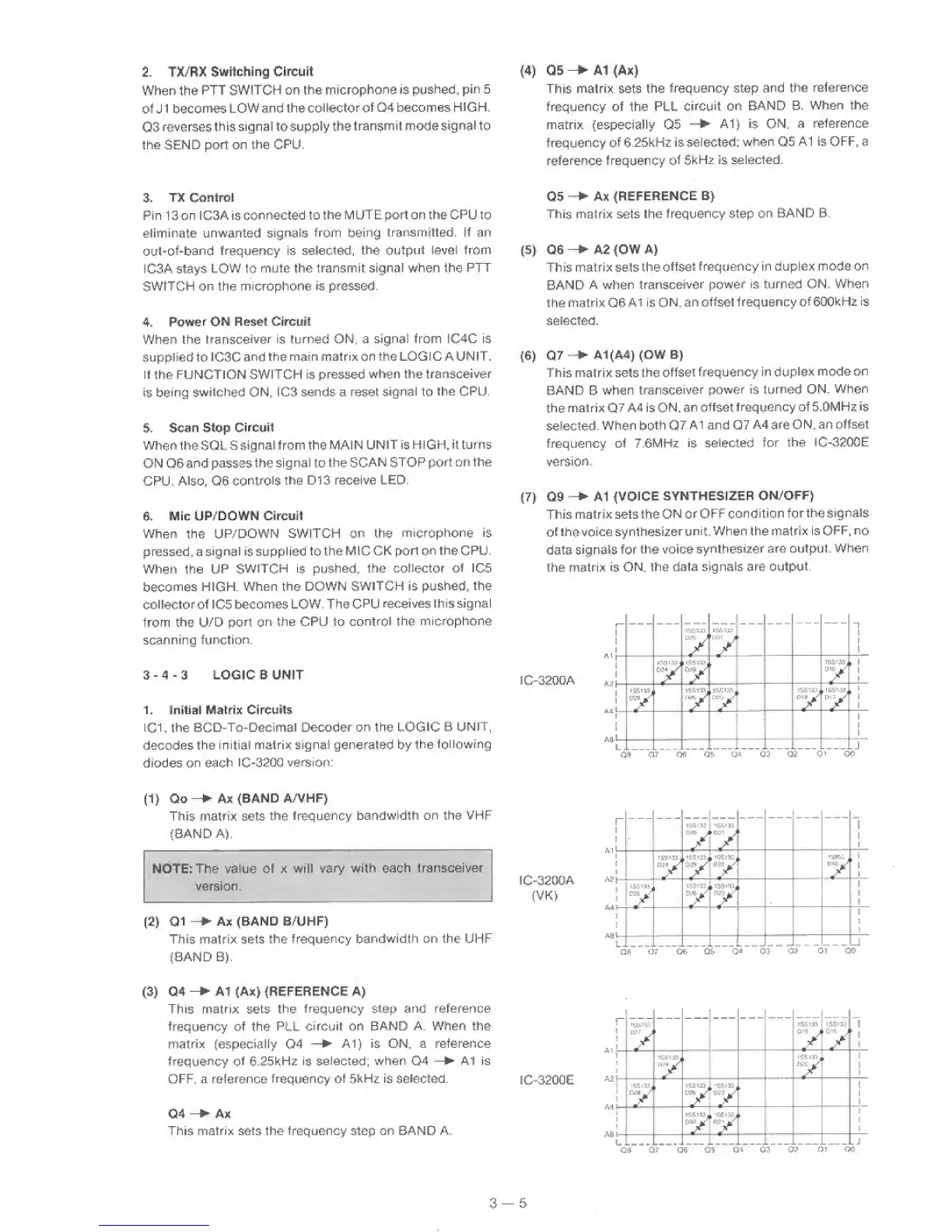
1. Initial Matrix CircuUs
IC1,
the
BCD-To-Decimal Decoder on the
LOGIC
B
UNIT,
decodes
the
initial
matrix signal generated by
the
following
diodes on
each
lC-3200
version:
(4)
Q5
-
A1 (Ax)
This
matrix
sets
the
frequency step and
the
reference
frequency of the PLL
circuit on
BAND B.
When the
matrix (especially Q5
—
At) is ON, a
reference
frequency of
6.25kHz is
selected;
when Q5
At is OFF, a
reference frequency
of
5kHz
is
selected.
Q5
Ax
(REFERENCE
3
}
This
matrix sets the
frequency
step
on
BAND B.
(5)
Q6->^A2(OWA)
This
matrix
setstheoffset
frequency
in duplex mode
on
BAND
A
when
transceiver
power is
turned ON. When
the matrix Q6 A1
is ON,
ani offset frequency
of
600kHz is
selected.
(6)
Q7
-A1(A4KOWB)
This matrix sets the
offset
frequency in
duplex
mode
on
BAND B when
transceiver
power is turned
ON.
When
the
matrix
Q7
A4 is
ON, an offset
frequency of 5.0MHz is
selected.
When
both
Q7
A1 and Q7
A4
are
ON,
an offset
frequency of
7.6MHz
is
selected for
the
IC-3200E
version.
(7)
09 A1
(VOICE
SYNTHESIZER
ON/OFF}
This matrix setsthe
ON or
OFF
condition
forthe
signals
of
the voice
synthesizerunit,
When
the matrix is
OFF.
no
data
signals
for
the voice
synthesizer
are output. When
the
matrix
is ON,
the data signals are
output.
r~
1
1
All-
15£1U
J
y
is&i;iii
^001
J
y
1
-
1
IC-3200A
A?!—
kSSi.53j
’y
*
iSS>3J,
1
1
A' 1
iSSiM,
15.5133.
Thi*
^
A
.15513a
y
.
ISElLtJj
y
h
[
Aq 1
AaJ'
s
—
L.
.J
Qfl.
07
Ofi 0&
Q.'.
Q3 02
01
QO
(1)
Qo Ax
(BAND A/VHF}
This matrix sets
the
frequency
bandwidth on the VHF
(BAND
AJ.
NOTE: The value of x will
vary with each
transceiver
version.
{
2
}
01
Ax (BAND B/UHF)
This matrix sets
the
frequency
bandwidth on the UHF
(BAND B).
IC-3200A
(VK)
(3)
Q4
-
A1 (AX>
(REFERENCE A)
This
matrix
sets
the
frequency
step and reference
frequency
of
the
PLL
circuit
on
BAND A. When the
matrix
fespecialiy
04
—
A1)
is ON,
a reference
frequency
of
6.25kHz
is selected;
when
Q4
—
A1 is
OFF, a reference
frequency of
5kHz
is selected.
IC-3200E
Q4
-
Ax
This
matrix
sets
the frequency step on BAND A,
I
r
iS5'33
y
j
/
iSSiM
y
1
^
(
1
iSilSjj
y
h
IS512J.
y
¥
1
1
1
—
a5Sii3,
y
ISS133
*
1
1
1
1—
'
1
1
1
h
y
1
jAS 1
U ,
y
*
1
1
1
I. .J
07
06 05
Qi
03 Q?
01 0<5
3
—
5
 Loading...