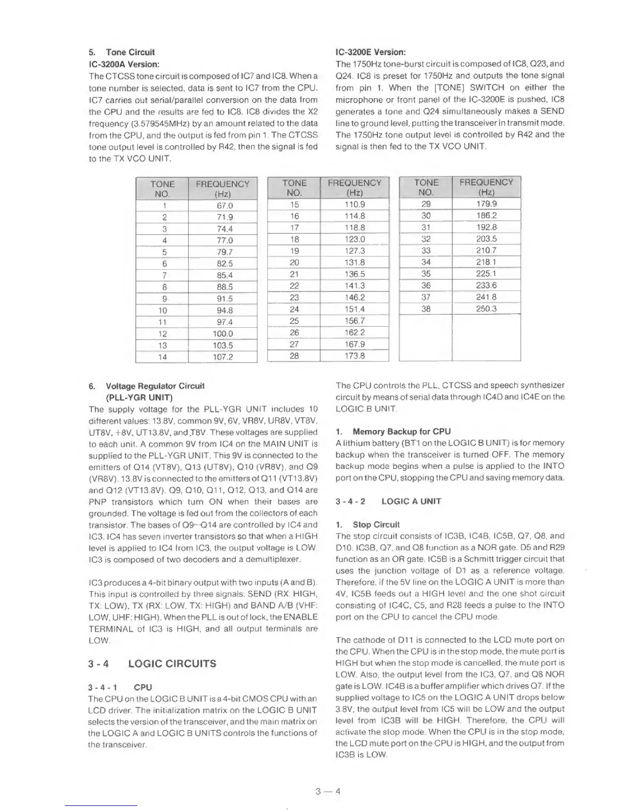
5. Tone Circuit
IC-32D0A Version:
TheCTCSStorectrcuit is composed
of iC7
and
IC8.
When a
tone number is selected, data is
sent
to
IC7
from the CPU.
IC7 carries
out
aeriai/parallei conversion on the data
from
the CPU and the results are fed to tCS, IC8
divides
the X2
frequency
(3,579545MHz)
by
an amount related to the data
from the CPU^ and the output
is fed
from
pi n 1 . The CTCSS
tone
output
level is controfled by
R42,
then
the signal is fed
to
the
TX
VCO
UNIT.
IC-3200E Version:
The 1 750Hz
tone-burst
circuit
iscomposed of 3CS,
Q23,
and
Q24.
ICS
is preset for 1750Hz and outputs
the tone
signal
from
pin 1. When the
[TONE]
SWITCH on
either the
microphone or front
panel of
the
IC-3200E
Is pushed, ICS
generates
a
tone
and
024
simultaneously
makes
a
SEND
line to
ground
level,
putting
thetransceiver in transmit mode.
The 17S0Hz tone output
Jevel
is
conIrolSed
by R42 and the
signal Is then fed to the TX VCO UNIT.
TONE FREQUENCY
NO.
(Hz)
1
67.0
2
71
9
3 74.4
4 77.0
5 79,7
6
82.5
7
85,4
S 8S.5
9
91.5
10 94,8
11 97.4
12 100.0
13 103.5
14 107.2
TONE
1
FREQUENCY
NO. (Hz)
15
110.9
16
114.8
17
118.8
18 123,0
19 127,3
i
20
131.8
21
1
136.5
22
141.3
23 146.2
24
151.4
25 156.7
_ .
.
.
26
1622
27
167.9
28 173.8
TONE
NO.
FREQUENCY
(Hz)
29
179,9
30
106.2
31 192,8
32
203,5
33
210.7
34
218.1
35
225.1
36 233,6
37
241.8
38 250.3
6. Voltage
Regulator
CircutI
{PLL-YGR
UNIT)
The supply voltage for the PLL-YGR
UNIT
includes
10
different
values:
13.3V,
common
9V, 6V, VR8V, UR8V,
VT8V,
UT8V, +8V,
UT13.8V,
and
J8V.
These
voltages are supplied
to each unit. A
common
9V
from
IC4
on the MAIN UNIT is
supplied to the PLL-YGR
UNIT.
This
9V
is
connected to the
emitters of
Q14
(VT8V),
Q13
(UT8V). QIO
(VRSV), and
Q9
(VRBV). 13.8V isconnected to
theemittersofQII
(VT13.8V)
and
012
(VT13.SV).
Q9,
QIO, Oil,
Q12,
Q13,
and Q14 are
PNP
transistors
which turn ON when their bases
are
grounded.
The
voltage
is fed
out
from the collectors
of
each
transistor.
The
bases
of
09^
014 are
controlled by lC4and
IC3. IC4 has seven
inverter transistors
so
that
when
a HIGH
level is applied to IC4 from IC3,
the
output
voltage is LOW.
IC3 is composed
of
two
decoders
and
a demultipiexer,
I
C3
produces a 4-bit binary output with
two inputs
(A
and
B).
This input
is
controlled by three
signals; SEND
(RX:
HIGH,
TX:
LOW),
TX (RX; LOW, TX: HIGH) and BAND A/B
(VHP;
LOW. UHF;
HIGH),
When the
PLL is
out
of lock, the ENABLE
TERMINAL
of
ICS
is
HIGH,
and
all output terminals
are
LOW.
3-4
LOGIC
CIRCUITS
3-4-1
CPU
The CPU
on the
LOGIC
B
UNIT
is
a4-bit
CMOS CPU with an
LCD
driver.
The initialization
matrix
on
the LOGIC B UNIT
selects
the
version of
the
transceiver,
and the main matrix on
the
LOGIC
A
and
LOGIC
B UNITS controls the functions of
the transceiver.
The
CPU controls the
PLL, CTCSS and speech synthesizer
ci rcuit by means
of
serial data
through I
C4 D and I G4E on the
LOGIC
B UNIT.
1. Memory Backup for CPU
A lithium battery (BT1 on the LOGIC B
UNIT) isfor memory
backup when the transceiver is turned
OFF.
The memory
backup mode begins when a pulse is applied to the
INTO
port
on
the CPU,
stopping
the CPU and saving memory data.
3-4-2
LOGIC
A
UNIT
1. Stop Circuit
The stop circuit consists of tC3B, iC4B,
IC5B,
Q7.
Q6,
arid
DIO. IC3B,
Q7,
and Q8
function
as a
NOR
gate.
D5
and
R29
function as an OR gate. IC5B is a Schmitt trigger ci
rcuit that
uses
the
junction voltage of D1 as a
reference
voltage.
Therefore,
if the 5V line on the LOGIC
A
UNIT
is
more than
4V,
IC5B
feeds
Out
a HIGH level and the one shot circuit
consisting of
IC4C,
C5,
and
R28
feeds
a pulse to the INTO
port on the
CPU
to
cancel the CPU
mode.
The cathode of Dll is connected to the
LCD
mute
port on
the
CPU.
When the CPU is in the stop mode,
the
mute
port
is
H
IGH
but when the stop mode
is
cancelled,
the mute port is
LOW. Also, the output levef from the IC3,
Q7,
and Q3 NOR
gate
is LOW.
ICABisabufferampiifier which drivesQZ. if the
supplied
voltage to 1C5 on the LOGIC A UNIT
drops below
3.8V,
the
output
level from 105 will be LOW and the output
level from IC3B
will be HIGH. Therefore, the
CPU
will
activate the stop mode. When the
CPU
is
in
the
stop
mode,
the LCD mute port on the CPU is HIGH,
and the outputfrom
JC3B is
LOW,
3
—
4
 Loading...