An external ALC
input from the [ALC]
jack or
the
[ACC] The selected
AF
signal
is
applied
to the AF amplifier circuit
sockets
is applied to the buffer amplifier
(Q4).
External
ALC in the MAIN
unit,
operation is
identical
to that
of the internal
ALC.
4-2-10
APC CIRCUfT
(IF
UNIT)
4-2-13
RF, SWR, ALC, COMP, Id,
Vd
METER
CIRCUITS (IF UNIT)
The APC
(Automatic Power
Control)
circuit
protects the
power amplifiers on the PA unit from high
SWR
and
exces-
sive current.
The reflected
wave signal appears and increases on
the
antenna
connector
when
the antenna is mismatched.
D1
of
the SWR
detector circuit
(L2, D1,
D2) in
the CTRL unit
detects
the
signal and
applies
it to IC2a in the IF unit as
the
“REF” signal.
When the “REF”
signal level increases,
lC2a
decreases
the
“ALC” voltage via IC1 b to
activate
the ALC.
For the current APC, the
power transistor
current is ob-
tained by
detecting the voltages (“ID-i-" and
“ID-”) which
appear
at
both terminals of a
0.012
Q
resistor
(R35)
on
the
PA
unit. The detected voltage is applied to
the
differential
amplifier (ICIa pins
2,
3).
When the current
of
the
final
transistors is
more
than 1
8
A,
IC1
a
controls the
ALC line via
IC1 b to
prevent excessive current flow.
When activating the antenna tuner
with manual tuning, the
"PODN” signal
turns
Q7 ON.
As a result, the
“POC” voltage
is
shifted to reduce the output power to
50
W.
4-2-11
TEMPERATURE PROTECTION
CIRCUIT (PA UNIT)
The
cooling fan
(MF1) is activated while transmitting
or if
the
temperature of the
final
transistors exceeds the preset
value.
While
transmitting,
Q5
and 08
are turned
ON, and provide
a
voltage
to
MF1. MF1 rotates
at
medium
speed
in
this
case.
Thermistor
R29
detects
the
temperature
of
Q4b.
When the Q4b temperature exceeds
60°C
(140T),
R29
activates
07
and
09 to
accelerate
the
cooling
fan. MF1
rotates
at
high speed
at
80
“C
(176T)
or
more.
R29 keeps the cooling
fan rotating even
when receiving
until the
Q4b
temperature drops
to
40
°C (104°F)
or below.
While
transmitting,
RF, SWR,
ALC, COMP, Id or Vd meter
readings
are
available
and can be selected with
the
[METER] switch.
(1
)
Power
meter circuit
The “FOR" voltage
from
the CTRL
unit is applied to the
power meter
amplifier (IC2b pin
5).
The “POM” signal from
IC2b
(pin
7)
is
applied
to
the
meter switch (IC6 pin
15).
R456
and
C21 0
are used for peak
hold.
(2)
SWR
meter
circuit
The
“FOR” voltage, amplified
at IC2b, is applied to the
SWR
meter
circuit
(IC4, ICS,
01,
02).
The “REF” voltage, ampli-
fied
at
lC2a,
is also applied to the
SWR meter circuit.
IC4b
outputs a
signal
according to the
ratio of “FOR” to “REF”
voltage.
The
signal is
applied to the meter switch
(IC6 pin
14).
(3)
ALC meter circuit
The ALC bias
voltage
is applied to the inversion-amplifier
(IC3b pin
6)
and is then applied
to the meter switch
(IC6
pin
12
).
(4)
COMP
meter circuit
A portion of
the
RF speech
compressor
(035)
output is
detected at
D33, applied to the buffer-amplifiers
(037,
IC7a
pin
3),
and is
then applied
to
the meter switch
(IC6 pin
1).
(5)
ID meter
circuit
A portion of the current APC circuit
(IC1 a) output is applied
to the meter
switch (IC6 pin
5)
via R31
9.
(6)
Vd meter circuit
The
“ID-” voltage is divided
at R326 and
R327
and
is
applied
to the meter switch
(IC6
pin
2).
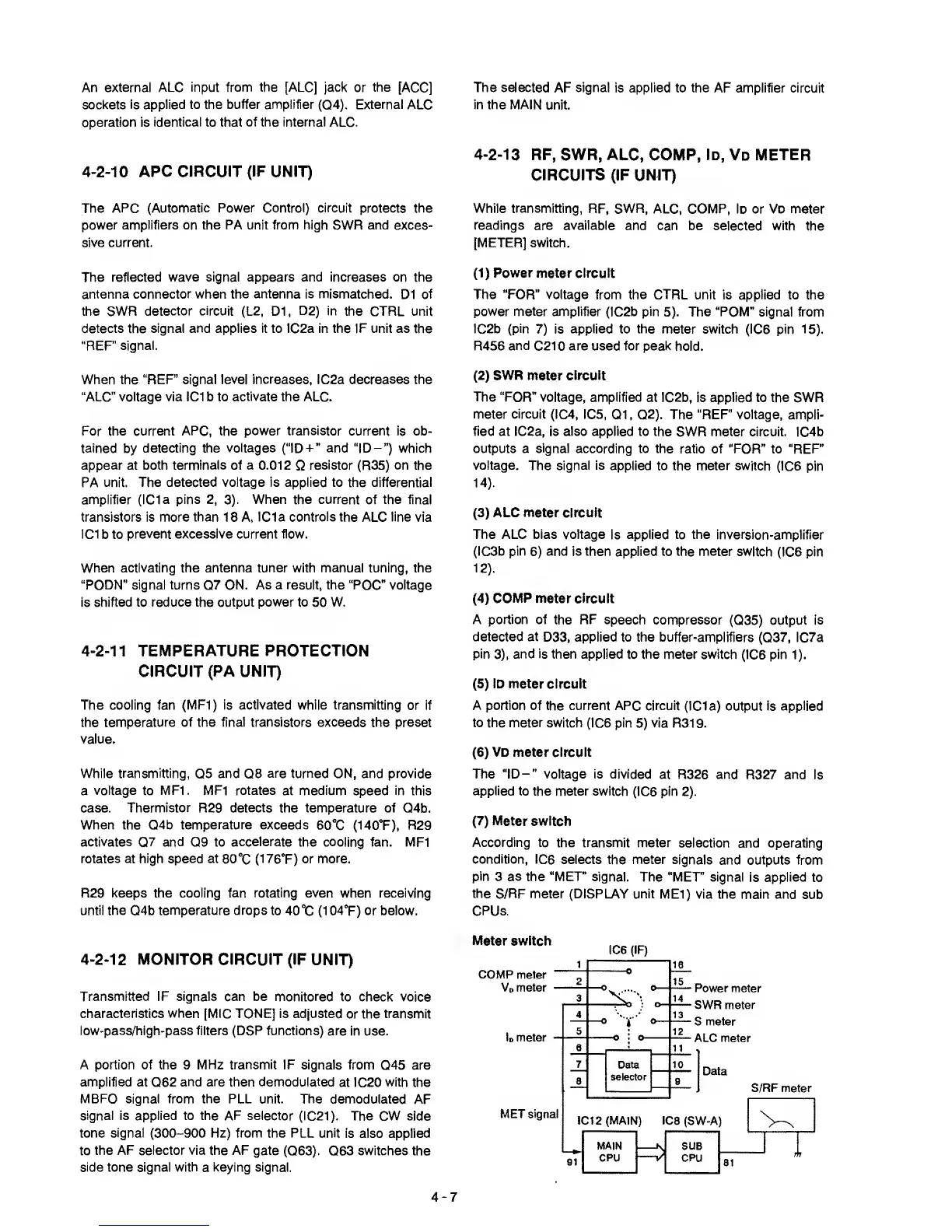
(7)
Meter
switch
According to the
transmit meter
selection and operating
condition, IC6
selects the meter
signals and outputs from
pin
3
as
the “MET signal.
The “MET” signal
is
applied
to
the
S/RF
meter
(DISPLAY unit
MEl) via the main and
sub
CPUs.
4-2-12
MONITOR CIRCUIT (IF
UNIT)
Transmitted IF signals can be monitored
to check voice
characteristics when
[MIC TONE] is adjusted
or the
transmit
low-pass/high-pass filters
(DSP functions) are
in use.
A portion of the 9 MHz
transmit
IF signals from
045 are
amplified at 062
and are
then
demodulated
at IC20
with
the
MBFO signal from the
PLL unit.
The
demodulated
AF
signal is applied to the AF selector
(IC21). The CW
side
tone
signal
(300-900 Hz) from the PLL unit
is also applied
to
the AF selector via the AF
gate
(063).
063
switches
the
side tone signal
with
a
keying signal.
Meter switch
IC6
(IF)
4-7