5 - 3
5-2 TRANSMIT AMPLIFIER ADJUSTMENT
Select an adjustment item using [2]
/ [8] keys, then set the adjustment value as specifi ed using [DIAL].
ADJUSTMENT ADJUSTMENT CONDITION OPERATION
ADJUSTMENT
ITEM
VALUE
IDLING CURRENT
(@5.0 V)
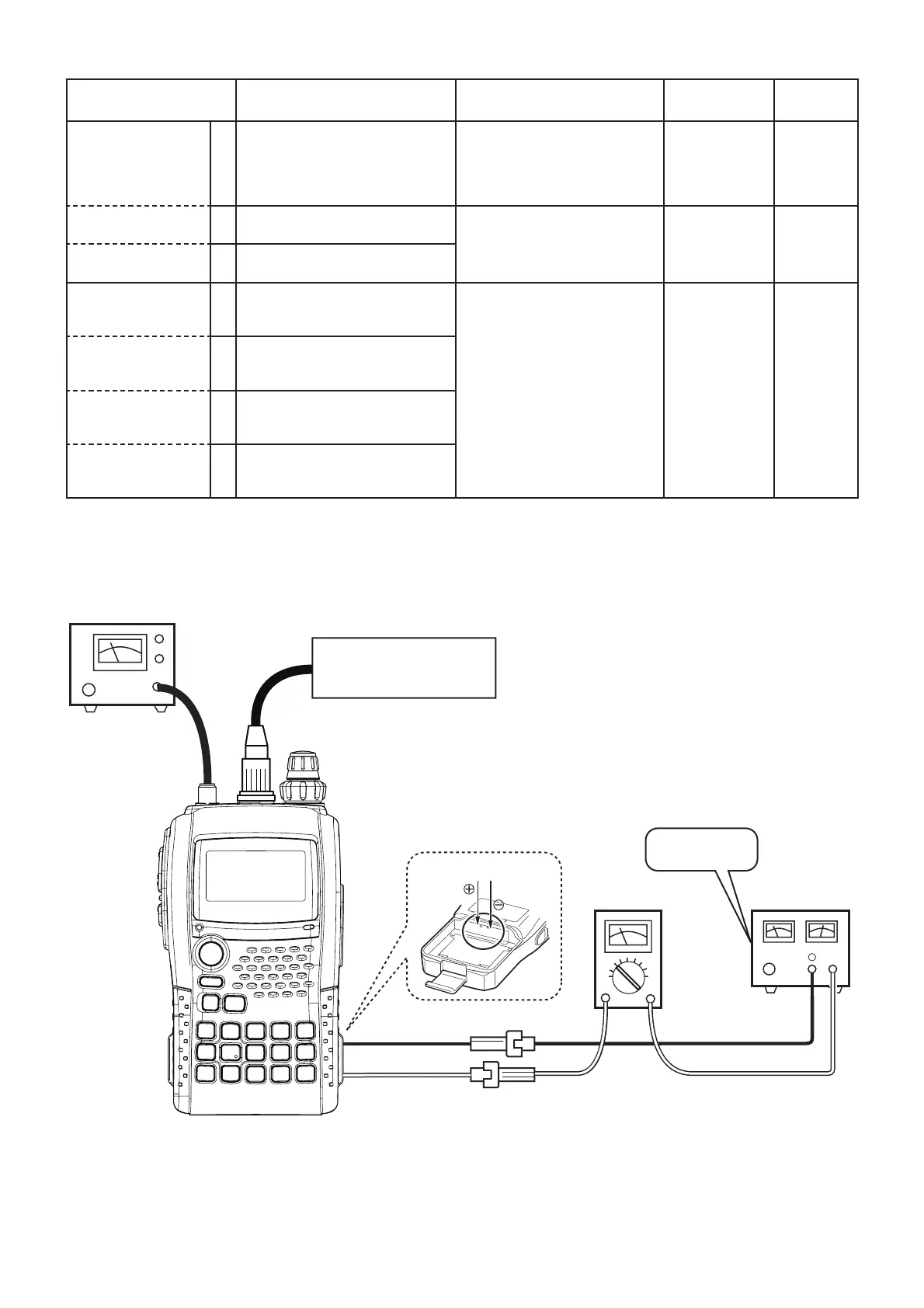
[PREPARATION]
0 • Supply voltage : 5.0 V 1) Connect an RF power meter
to the antenna connector.
2) Connect a multimeter
between the external power
supply and transceiver.
––
[VHF BAND] 1 • Displayed freq. : "
"
• Transmitting
• Adjust the current using
[DIAL], then release the PTT
and push [BAND] to store the
adjustment value.
[
KF
]
200–300
mA
[UHF BAND] 2 • Displayed freq. : "
"
• Transmitting
TRANSMIT
POWER (@5.0 V)
[VHF (BAND LOW)]
1 • Displayed freq. : "
"
• TX power : "
5.1
"
• Transmitting
• Adjust the TX power using
[DIAL], then release the PTT
and push [BAND] to store the
adjustment value.
[
2Q
] 50–150 mW
[VHF (BAND HIGH)] 2 • Displayed freq. : "
"
• TX power : "
5.1
"
• Transmitting
[UHF (BAND LOW)] 3 • Displayed freq. : "
"
• TX power : "
5.1
"
• Transmitting
[UHF (BAND HIGH)] 4 • Displayed freq. : "
"
• TX power : "
5.1
"
• Transmitting
To the battery contact pins
JIG cable
(See the page 5-1)
5.0 V
Fusese
(3A)
DC power supply
⊕
−
–
+
MULTIMETER
(10 mA to 3 A)
+
−
RF POWER METER
(10 W/50 Ω)
Be sure the polarity.
(4
#(/
5.1

 Loading...