EasyManuals Logo

Icom IC-A16 User Manual

Icom IC-A16
35 pages
To Next Page IconTo Next Page
To Previous Page IconTo Previous Page
Page #11 background imageLoading...
Page #11 background image
3-2
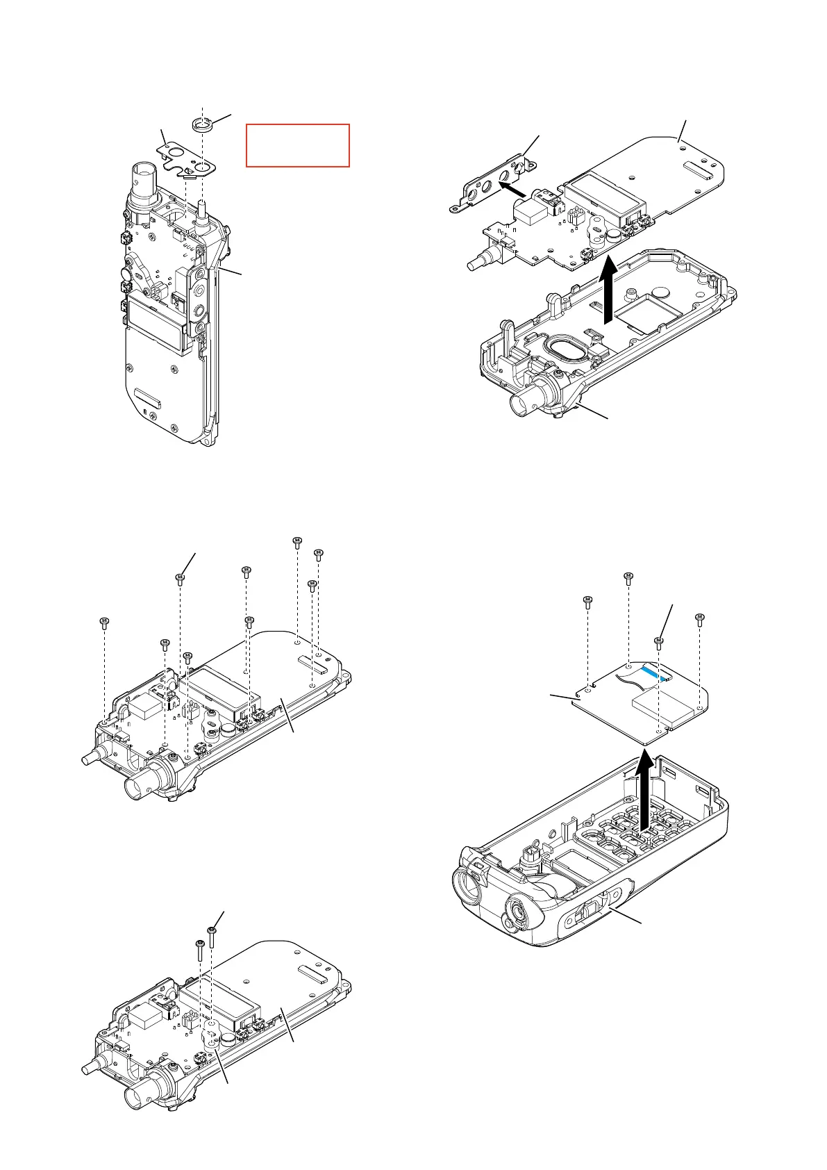
2. REMOVING THE MAIN UNIT
1) Remove the volume nut from the top of the chassis, and
then remove the top plate.
4) Remove the side plate from the MAIN UNIT, and then
remove the MAIN UNIT from the chassis.
2) Remove the 9 screws from the MAIN UNIT.
3) Remove the 2 screws from the heatsink of MAIN UNIT.
Chassis
MAIN UNIT
Side plate
3. REMOVING THE FRONT UNIT
1) Remove the 4 screws, and then remove the FRONT
UNIT from the front panel.
Screws ×4
Front panel
FRONT UNIT
Chassis
Volume nut
Top plate
Remove with;
“ICOM Driver (AG)”
(8960000561)
MAIN UNIT
Screws ×9
MAIN UNIT
Heatsink
Screws ×2

Other manuals for Icom IC-A16

Questions and Answers:

Question and Answer IconNeed help?

Do you have a question about the Icom IC-A16 and is the answer not in the manual?

Icom IC-A16 Specifications

General IconGeneral
Channel Spacing8.33 kHz/25 kHz
Number of Memory Channels200 channels
Antenna Impedance50 Ω
WaterproofIP67
DisplayLCD
Frequency Range118.000–136.9916 MHz
Output Power6 W (PEP), 1.8 W (carrier)
WeightApprox. 300 g (with standard battery)
Power Supply Requirement7.2 V DC
Current Drain (Transmit)1.5 A
ModeAM
Channels200
Voltage7.2V

Related product manuals