SECTION 4 ADJUSTMENT PROCEDURE
4-1
SECTION 4 ADJUSTMENT PROCEDURE
4-1 PREPARATION
■ REQUIRED EQUIPMENT
EQUIPMENT GRADE AND RANGE EQUIPMENT GRADE AND RANGE
Programming
software
CS-A16 PROGRAMMING SOFTWARE
(Revision 1.01 or later)
Programming cable OPC-478UC
JIG cable See the illustration below.
Battery pack BP-280 (Fully charged) AC millivoltmeter Measuring range: 10 mV to 10 V
Frequency counter
Frequency range: 0.1~300 MHz
Frequency accuracy: ±1 ppm or better
Audio generator
(AG)
Frequency range: 300~3000 Hz
Output level: 1~500 mV
RF power meter
(50Ωterminated)
Measuring range: 0.1~10 W
Frequency range: 100~300 MHz
SWR: Less than 1.2 : 1
Standard signal
generator (SSG)
Frequency range: 0.1~300 MHz
Output level: –20 to 90 dBµ
(–127 to –17 dBm)
Modulation
analyzer
Frequency range: 30~300 MHz
Measuring range: 0 to ±10 kHz
Attenuator
Power attenuation: 30 dB
Capacity: More than 10 W
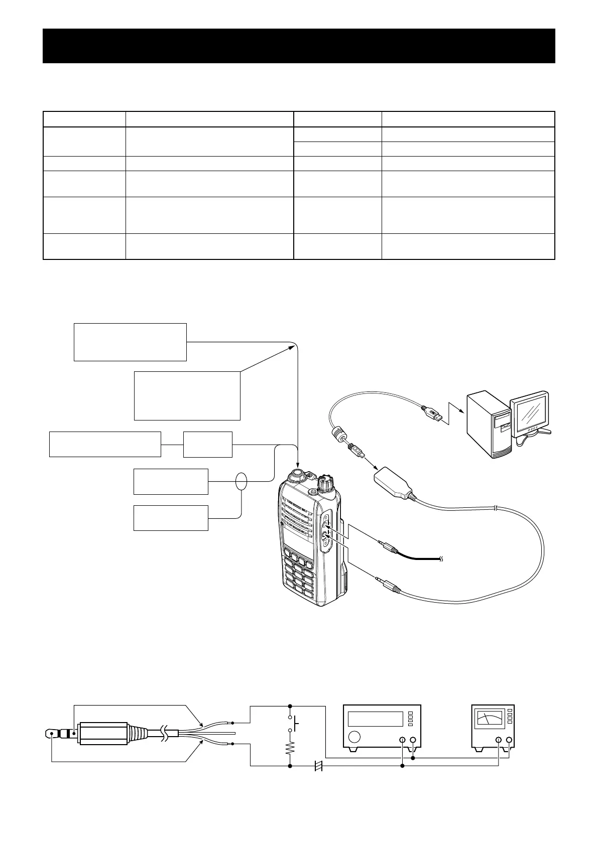
■ CONNECTION
Modulation analyzer
30~300 MHz/0 to ±10 kHz
to the antenna connector
Attenuator
30 dB
RF power meter
0.1~10 W/50 Ω
Frequency
counter
Standard signal generator
–20 to 90 dBµ
(–127 to –17 dBm)
CAUTION!
NEVER transmit while
the SSG is connected to
the antenna connector.
PC
to USB port
OPC-478UC
IC-A16/IC-A16E
JIG cable
To [MIC]
To [SP]
Loose couple
■ JIG CABLE
+ −
AC MILLIVOLTMETER
(10 mV to 10 V)
+ −
AUDIO GENERATOR
(300~3000 Hz/1~500 mV)
3-conductor 2.5 (d) mm plug
(MIC)
(MIC)
(GND)
(GND)
33 kΩ
PTT
4.7 µF
+