AUDIO WIRING
Use #24 AWG wires for connectors.
MEMORY CHANNEL AND FREQUENCY
EXCHANGE SWITCHES
For the memory channel switch and frequency exchange
switch, use a 2-position rocker switch or 2 separate
momentary push switches.
POWER CABLE WIRING
Use 2 pairs of #18 AWG wires for power and power
grounding wiring.
• Circuit breaker
To prevent physical damage, a 10 A circuit breaker
MUST
be installed in the aircraft. Mount the circuit breaker in the
aircraft breaker panel or instrument panel to ensure easy
access during flight.
• Ground
The transceiver power ground is the airframe ground.
• jumpers
Pins 11, M, P, 13 MUST be jumped together with AWG
#20 wires or thicker.
TRANSMIT/RECEIVE INTERLOCK WIRING
When 2 transceivers are installed and both communication
antennas are top mounted, pin N
MUST be connected to
pin 9 of each another transceiver.
INTERNAL FUSE
The IC-A200 has a 5 A internal fuse. If the power does not
turn ON, open the top cover and check the fuse.
DIMMER SELECTION
Connect pin B to the Instrument panel lighting line.
When the instrument panel lighting switch is placed to
dimmer position, the transceiver backlighting is reduced to
half brightness.
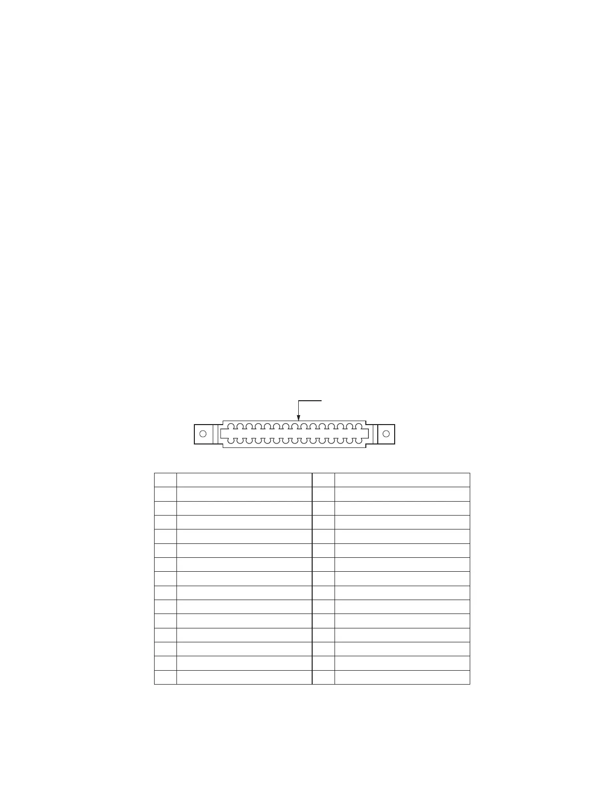
5-2 MOLEX CONNECTOR
A No connection 1 Ground for pin B
B +14 V lighting (input) 2 Detected audio (output)
C Auxiliary audio 2 (input) 3 Auxiliary audio 3 (input)
D Auxiliary audio 1 (input) 4 Ground for pins D, C, 3
E 4 Ω audio (output) 5 Ground for pin E
F Power ground 6 Power ground
H 500 Ω audio (output) 7 Ground for pin H
J Comm microphone (input) 8 Ground for pins J, K, 9
K Intercom microphone (input) 9 PTT*
L Memory channel switch* 10 Squelch cancel*
M + 13.8 V power (input) 11 +13.8 V power (input)
N Transmit/receive interlock 12 Frequency exchange switch*
P Switched aircraft power (output) 13 Switched aircraft power (output)
R Aircraft (input) 14 Aircraft power (input)
S Power ground 15 Power ground
*Ground to activate.

 Loading...