6-2 PLL ADJUSTMENT
6-3 RECEIVER ADJUSTMENT
ADJUSTMENT ADJUSTMENT CONDITIONS
MEASUREMENT
VALUE
ADJUSTMENT
POINT
UNIT LOCATION UNIT ADJUST
REFERENCE
OSCILLATOR
1 • Frequency display: 118.000 MHz
• Receiving
MAIN Connect the frequency
counter to J31.
32.000000 MHz MAIN C199
LOCK
VOLTAGE
1 • Frequency display: 118.000 MHz
• Receiving
MAIN Connect the DC voltmeter
to J30.
2 V ±0.1 V VCO C2015
2 • Frequency display: 136.975 MHz More than 5 V Verify
ADJUSTMENT ADJUSTMENT CONDITIONS
MEASUREMENT
VALUE
ADJUSTMENT
POINT
UNIT LOCATION UNIT ADJUST
2nd LO LEVEL
1 • Frequency display: 118.000 MHz
• Receiving
MAIN Connect the RF voltmeter
to J31.
Maximum level
(more than –3 dBm)
MAIN L26, L27
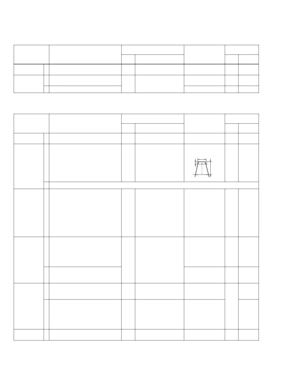
BANDPASS
FILTER
1 • Frequency display: 118.000 MHz
• J13: disconnected
• Connect the RF sweep generator to J1
and set as:
Center frequency : 118.025 MHz
Sweep band width: ±10 MHz
• Receiving
MAIN Connect the spectrum
analyzer to J27.
Set the band width as
follows.
MAIN L1, L2,
L3, L5
NOTE: After adjustment, connect the J13.
PEAK 1 • Frequency display: 118.000 MHz
• Connect the SSG to the antenna
connector and set as:
Modulation : 1 kHz 30%
Level : 1.0 µV *(–107 dBm)
• R35: Max. Counterclockwise
• R73: Max. Clockwise
• Squelch: Open (Pull OUT the volume
control.)
• Receiving
Rear
panel
C o n n e c t t h e A C
millivoltmeter to the AF
output terminal with a 4
Ω
load.
Maximum level
MAIN L16, L15,
L14, L10,
L8
TOTAL GAIN
1 • Frequency display: 118.000 MHz
• Connect the SSG to the antenna
connector and set as:
Modulation : 1 kHz 30%
Level : 1 mV *(–47 dBm)
• Receiving
Rear
panel
C o n n e c t t h e A C
millivoltmeter to the AF
output terminal with a 4
Ω
load.
0 dB on the meter Front
Panel
Volume
control
2 • Apply no signal to the antenna
connector.
Adjust R35 to a point
where the noise level
is 8 dB down.
MAIN R35
SQUELCH
1 • Frequency display: 118.000 MHz
• R67: Max. Counterclockwise
• Receiving
MAIN Connect the DC voltmeter
to J32.
2.5 V ±0.1 V MAIN R73
2 • Connect the SSG to the antenna
connector and set as:
Modulation : 1 kHz 30%
Level : 1.0 µV *(–107 dBm)
• Squelch: Close (Push IN the volume
control.)
Rear
Panel
Connect a speaker to the
AF output termianl.
Squelch just opens. R67
BEEP 1 • Push the frequency exchange switch. Rear
panel
Connect a speaker to the
AF output termianl.
Desired level
MAIN R83
6 - 2
*This output level of standard signal generator (SSG) is indicated as SSG’s open circuit.

 Loading...