6 - 4
6-4 TRANSMITTER ADJUSTMENT
ADJUSTMENT ADJUSTMENT CONDITIONS
MEASUREMENT
VALUE
ADJUSTMENT
POINT
UNIT LOCATION UNIT ADJUST
IDLING
CURRENT
1 • Disconnect P3
• Unsolder C.P. + and C.P. –.
• Frequency display : 127.000 MHz
• Transmitting
PA Connect the DC ammeter
(1 A) to point between
C.P.+ and C.P.–.
150 mA PA
R5005
NOTE: After adjustment, re-solder between C.P. + and C.P. –.
2 • Unsolder C.P. – and W4. PA Connect the DC ammeter
(1 A) to point between
C.P.– and W4.
200 mA PA
R5007
NOTE: After adjustment, re-solder between C.P. – and W4 and connect the P3.
BANDPASS
FILTER
1 • Frequency display : 118.000 MHz
• Connect the RF sweep generator to
J28 and set as :
Center frequency : 118.025 MHz
Sweep band width : ±10 MHz
• Transmitting
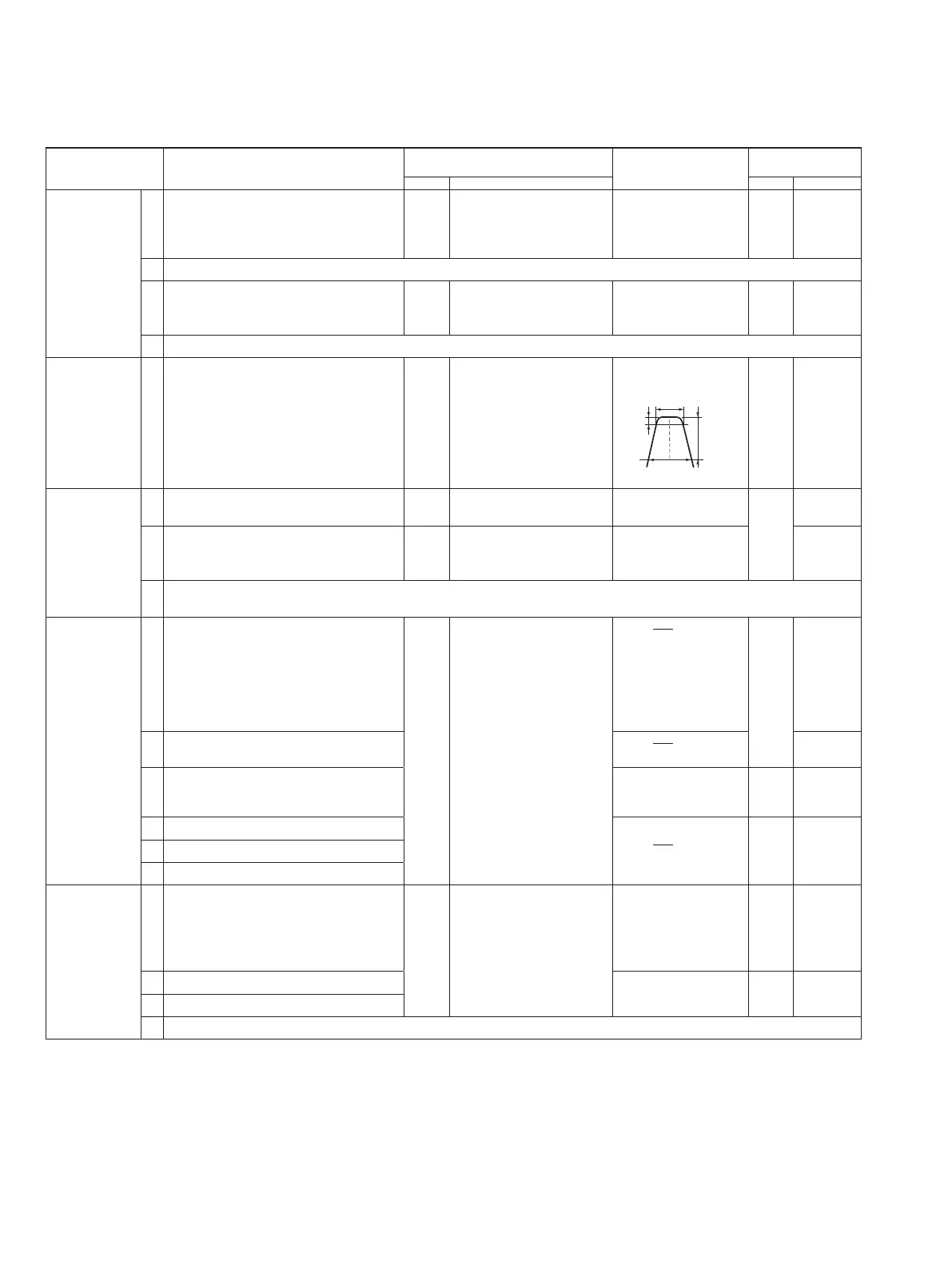
MAIN Connect the spectrum
analyzer to J2.
Set the band width as
follows.
MAIN L45, L46,
L47, L48
OUTPUT
POWER
1 • Frequency display: 118.025 MHz
• Transmitting
MAIN Connect the DC voltmeter
to J33.
3.2 V ±0.1 V MAIN R355
2 • Frequency display: 136.975 MHz Pear
panel
Connect the RF power
meter to the antenna
conector.
7.5 W
R337
NOTE: If the output power is less than 7.5 W in step 2, adjust R337 again so that the output power is 7.5 W on both
118.025 MHz and 1136.975 MHz.
MODULATION
1 • Frequency display: 127.500 MHz
• R131, R138: Center
• Connect the audio generator to the mic
input terminal and set as:
Level : 300 mV
Frequency : 1 kHz
• Transmitting
Rear
panel
Connect the modulation
analizer to the antenna
connector.
80% (
P-P
2
)
MAIN R138
2 • Set the audio generator as:
Level: 30 mV
35% (
P-P
2
)
R131
3 • Frequency display : 136.975 MHz
• Set the audio generator as:
Level: 300 mV
Minimum distortion
Ievel
PA
C5059
4 • Frequency display : 118.025 MHz More than
75% (
P-P
2
)
on each frequency
MAIN Verify
5 • Frequency display : 127.500 MHz
6 • Frequency display : 136.975 MHz
POWER
DOWN
1 • Frequency display : 136.975 MHz
• Unsolder low power line
• Apply no signal to the mic input
termianl.
• Transmitting
Rear
penal
Connect the RF power
meter to the antenna
conector.
3.5 W
MAIN R338
2 • Frequency display : 118.025 MHz More than 3 W Verify
3 • Frequency display : 127.500 MHz
NOTE: After adjustment, re-solder low power line.

 Loading...