DISASSEMBLY INSTRUCTION
1. REMOVING THE FRONT PANEL
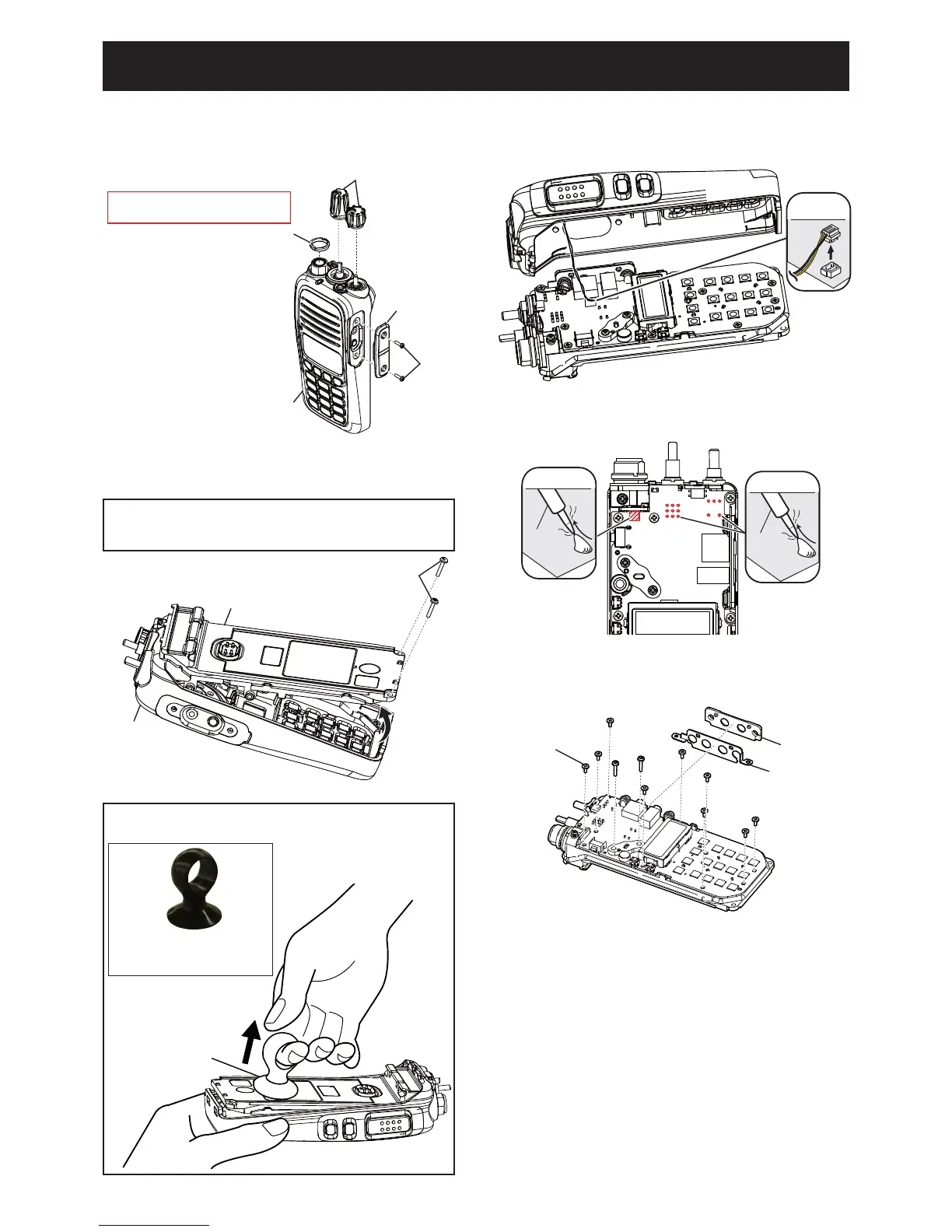
1) Remove the antenna connector nut and 2 knobs.
2) Remove 2 screws and jack panel.
2. REMOVING THE MAIN UNIT
1) Unsolder total of 15 points as shown.
3) Remove 2 screws from the bottom of the CHASSIS.
4) Lift the bottom of the CHASSIS up in the direction
of the arrow.
2) Remove 11 screws and the side panel and side
seal from the MAIN UNIT.
3) Remove the MAIN UNIT from the chassis.
BE CAREFUL when you disassemble the front panel from
the transceiver body. Otherwise the speaker cable and the
connector may be cut.
Remove with;
“ICOM Driver (K)” (8960000110)
ANTENNA CONNECTOR NUT
JACK PANEL
FRONT PANEL
SCRE
KNOB
UNSOLDER
Solder
remover
UNSOLDER
Solder
remover
SCREW×11
SIDE PANEL
SIDE SEAL
FRONT PANEL
CHASSIS
SCREW×2
SPEAKER
CABLE
5) CAREFULLY lift the chassis out of the front panel
and turn it over in order to unplug the speaker cable.
For easy separation of the CHASSIS
Use a suction lifter to lift the bottom of the CHASSIS up.
(Continued to the right above)
Suction lifter
Suction lifter
• Part name : EA950R-2
• Manufacture : ESCO CO.LTD
 Loading...