o
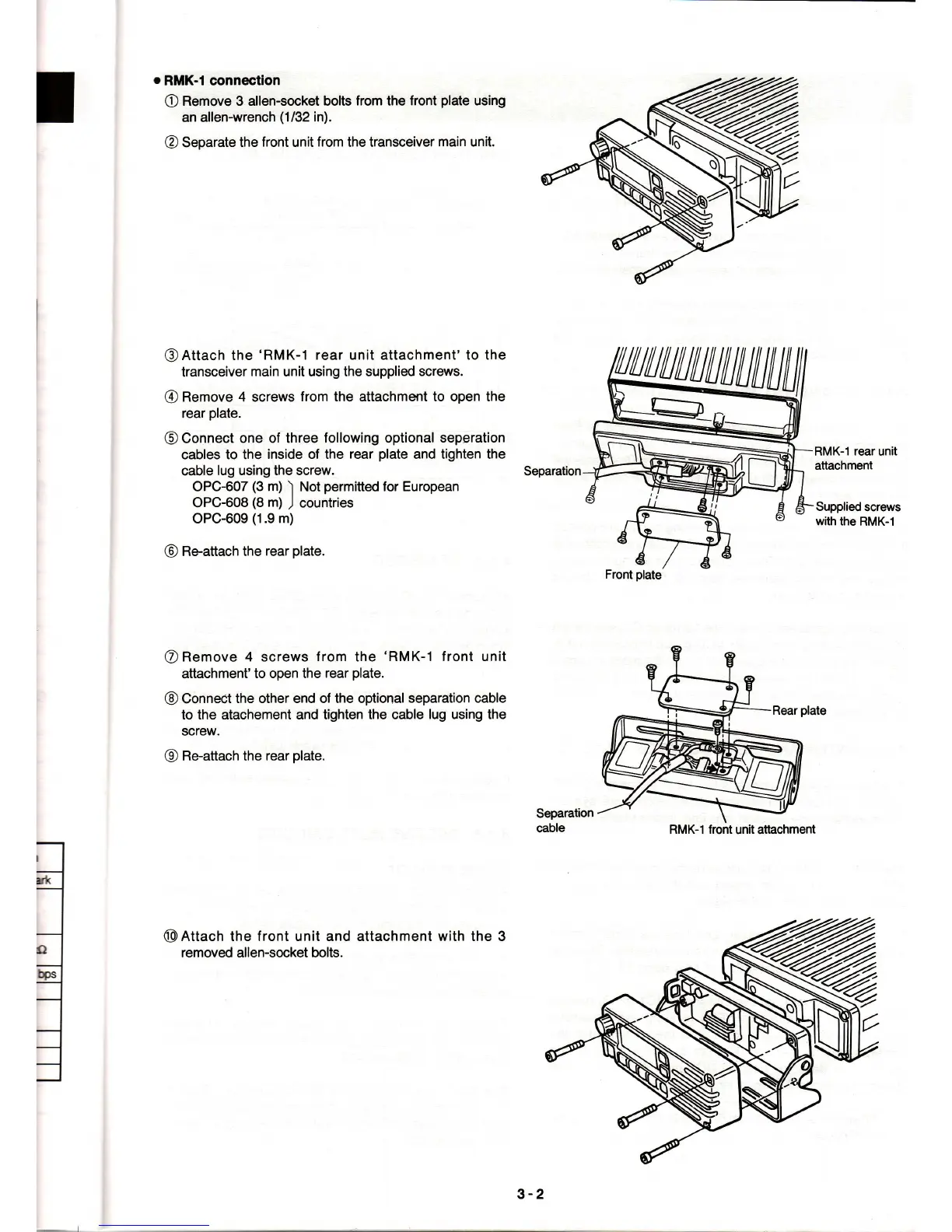
RMK-I connectaon
O
Remove 3 allen-socket bolts
from
the
front
plate
using
an allen-wrench
(1/32
in).
@
Separate
the front unit
from
the transceiver
main unit.
@Attach
the
'RMK-1
rear unit attachment' to the
transceiver
main unit using the supplied
screws.
@
Remove 4 screws
from the attachment to open the
rear
plate.
@
Connect
one of three
following
optional
seperation
cables to the
inside of the
rear
plate
and tighten the
cable
lug using the screw.
Separation
OPC-607
(3
m)
)
Not
permitted
for European
OPC-608
(8
m)
J
countries
OPC-609
(1.9
m)
@
Re-attach the
rear
plate.
O
Remove 4 screws
f
rom the
'RMK-1
front unit
attachment'to
open the
rear
plate.
@
Connect
the other end of the optional
separation cable
to the
atachement and tighten the cable
lug using the
screw.
@
Re'attach
the
rear
plate.
RMK-1
rear
unit
attachment
Supplied
screws
with the
RMK-1
Separation
cable
il
,l
@
Attactr the f ront unit and
removed allen-socket bolts.
attachment with the 3
RMK-1
front
unit attiachment
3-2
 Loading...