32
6
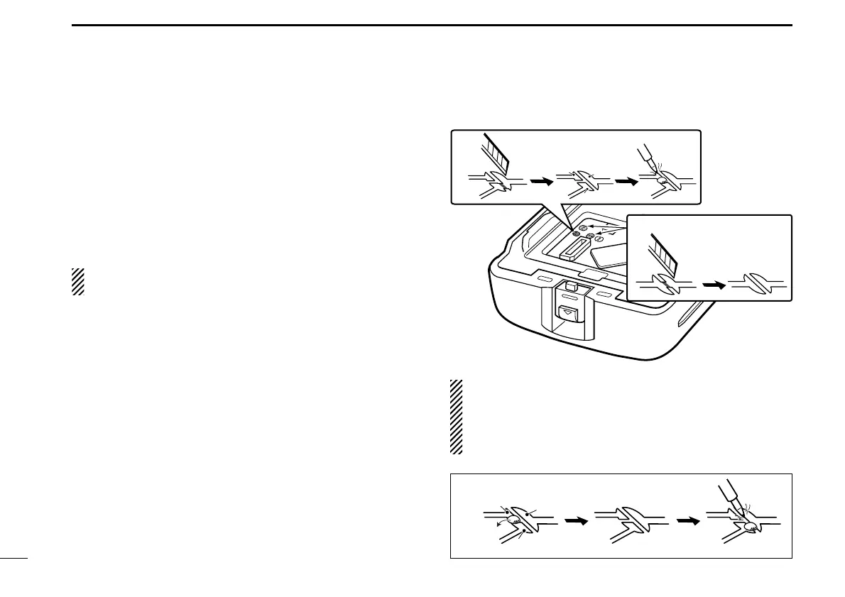
OPTIONAL UNIT INSTALLATION
The following PC board modification is required when
installing the optional UT-105, UT-117 or UT-117S:
q Rotate [VOL] to turn the power OFF, and remove the bat-
tery pack. (p. 2)
w Remove the unit cover as described in the Optional unit
installation (p. 30).
e Cut and solder the pattern on the PCB at the RX AF cir-
cuit as shown at right.
The next step r is necessary for the UT-117S installation.
Go to step t to install the UT-105 or UT-117.
r Cut the pattern on the PCB at the TX mic circuit (MIC) and
RX AF circuit (DISC) as shown at right.
t Install the UT-105/UT-117/UT-117S as described in the
Optional unit installation (p. 30).
y Replace the unit cover and the battery pack, then rotate
[VOL] to turn the power ON.
NOTE: When uninstalling the SmarTrunk 3G™ unit
Be sure to un-solder A and B, and re-solder B and C as
shown below, otherwise no AF output is available.
Moreover, the UT-117S is required to re-solder the TX mic
circuit (MIC) and RX AF circuit (DISC) (p. 31).
A
B
C
e
r
UT-117S only
■ UT-105, UT-117 and UT-117S installation
IC-F34_44GT_GS-1.qxd 04.9.24 10:26 AM Page 32 (1,1)
 Loading...