30
6
OPTIONAL UNIT INSTALLATION
■ Optional unit installation
Install the optional unit as follows:
q Rotate [VOL] to turn the power OFF, and remove the bat-
tery pack. (p. 2)
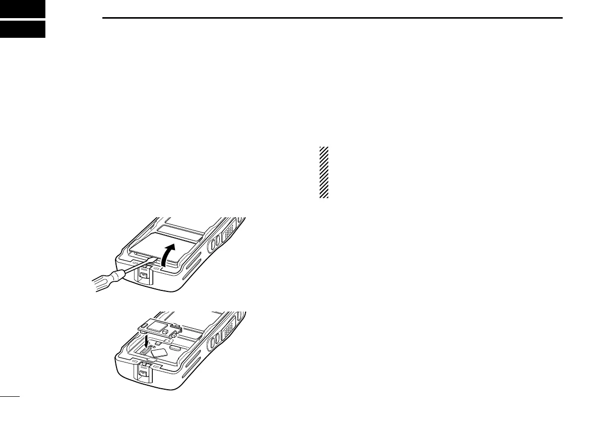
w Remove the unit cover.
NOTE: Use a flat head screw driver or a similar flat instrument,
and insert into the hollow of the chassis, then lift and take away
the unit cover.
Use the supplied spare unit cover! Do not use the cover that
has been removed once. Water or dust may get into the trans-
ceiver because the cover may be bent or has lost it’s adhesion.
This may result in the transceiver being damaged.
e Install the unit as shown below.
r Replace the unit cover and the battery pack, then rotate
[VOL] to turn the power ON.
NOTE: The optional UT-109/UT-110
SCRAMBLER UNITS
,
UT-105
SmarTrunk II™
LOGIC BOARD
or UT-117/UT-117S
SmarTrunk 3G™
LOGIC BOARD
requires some PC board modi-
fications. Please refer to the additional installation as
shown on pgs. 31 and 32.
*This illustration is
described with the
UT-113.
IC-F34_44GT_GS-1.qxd 04.9.24 10:26 AM Page 30 (1,1)
 Loading...