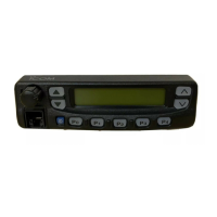
5-8 TRANSMITTER ADJUSTMENT for IC-F4/S
FM
DEVIATION
DTCS WAVE
FORM
1
1
• Operating freq. :
400.000 MHz (L-band)
440.000 MHz (ML-band)
470.000 MHz (MH-band)
490.000 MHz (H1/H2-bands)
• High/Low switch : Low
• Connect an audio generator to the
[MIC] jack and set as:
1 kHz/150 mV
• Set an FM deviation meter as:
HPF : OFF
LPF : 20 kHz
De-emphasis : OFF
Detector : (P–P)/2
• Transmitting
• Operating freq. :
415.000 MHz (L-band)
455.000 MHz (ML-band)
485.000 MHz (MH-band)
501.000 MHz (H1-band)
505.000 MHz (H2-band)
• High/Low switch : Low
• No audio applied to the [MIC] jack.
• DTCS code : 007
• Transmitting
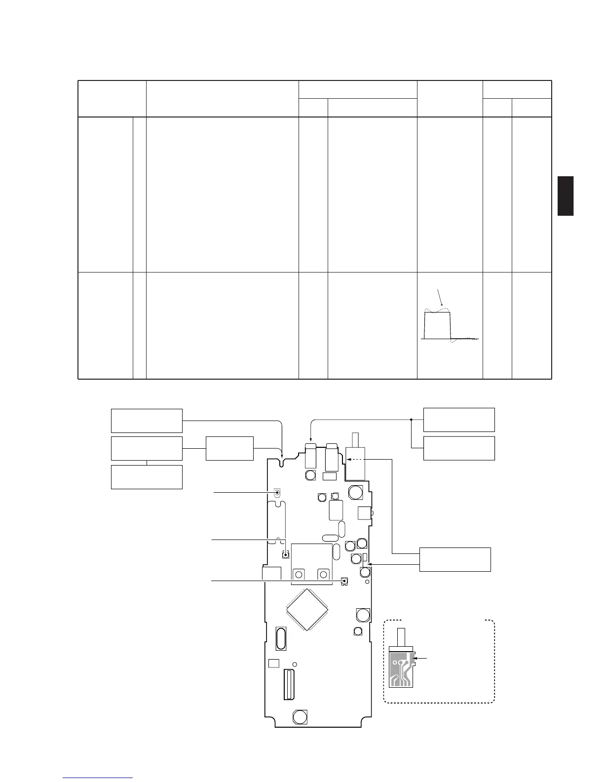
Top
panel
Top
panel
Connect an FM devia-
tion meter to the
antenna connector
through an attenuator.
Connect an FM devia-
tion meter with an
oscilloscope to the
antenna connector
through an attenuator.
MAIN
MAIN
R119
R150
ADJUSTMENT ADJUSTMENT CONDITIONS
UNIT LOCATION
VALUE
UNIT ADJUST
MEASUREMENT ADJUSTMENT
±4.1 kHz
(W-type)
±2.1 kHz
(N-type)
 Loading...